Atmel Motor Control
Posted: August 21, 2008
Introduction
This is a complete rewrite of my first microcontroller project done on a PIC microcontroller. The differences here are it runs on an Atmel Atmega168 chip a 20MHz instead of on a PICMicro at 4MHz. Also, it can control up to 8 servos instead of just 5 and each output channel can be configured as an RC airplane servo or a straight DC motor. I also changed the interrupt model significantly. For a schematic with DC motor control click here.
I posted the source code for the firmware already. The rest of the source code and a schematic will be posted at a later time.
Related Projects @mikekohn.net
Explanation
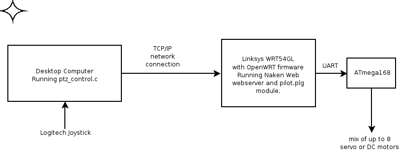
So I did this project basically because I was interested in implementing something similar to PTZ motors on security cameras. When I was working at my previous job, we'd have cameras like the Axis 213 which had a web interface to the pan/tilt/zoom motors for rotating the camera. I figured since my Naken Web web server can already emulate video coming from an Axis camera, it might be fun to make a plugin for it that can do the PTZ motor control too. I have a client side PTZ control that I wrote for fun for Linux's joystick device driver called ptz_control which I modified to send commands that Atmel Pilot understands. Since the Linksys WRT54GL can run OpenWRT Linux and had spots on the PC board for a serial port, I figured this would make a great embedded computer to test this on, especially since it has the wifi built in.
To view a diagram of the model I'm using for this project, click on the image below:
I'm currently using this firmware for my Linksys Quadcopter project
Atmel Pilot Firmware
So basically I wrote some motor control firmware here that I call Atmel Pilot, since I eventually want it to control motors for an RC plane or such. The firmware uses the UART of the ATmega168 to take commands from some other device/computer. Basically, the firmware takes 1 byte as input in this format:
7 6 5 4 3 2 1 0
V V V V V M M M
M = motor number
V = value from 0 to 20 to set the speed; 30 = set as servo ; 31 = set as DC motor
So basically if I went to set motor 0 to be a DC motor I would send a byte of: (31<<3)|0 which in binary would be 11111000 or in hex 0xf8. To make the speed of this motor 10 (half speed) I would send the byte: (10<<3)|0 which in binary would be 01010000 or in hex 0x50. The firmware on the chip will echo this number back so the software talking to the micro can see it went through correctly.
So what's the difference between a DC motor and the RC servo? The RC servo has 3 wires: Gnd, +5v, and signal. The +5 can be hooked up to a +5v source and gnd to gnd of course. The signal line is hooked up to the micro and expects a pulse of +5v every 20ms. The pulse width must be between 1ms and 2ms. The length of the pulse will tell the servo it's rotational position. For example 1ms could mean to turn all the way to the right, 1.5ms in the middle, and 2ms all the way to the left. There are airplane motors that take this configuration too, but they are hell-expensive, so I chose to make a DC motor control too.
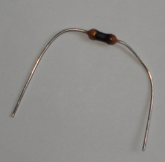
The DC motor is just 2 wires: + and -. Note: don't hook up a DC motor directly to a microcontroller or it will catch fire much in the way I got this resistor to catch fire: toasted_resistor.jpeg. How was I supposed to know that putting 12 watts through a 1/4 watt resistor would make it glow red and smoke :). Anyway, the DC motors work by pulse width modulation. During the 20ms period the servos are getting their pulses, the DC motor will get a pulse between 0 and 20ms depending how fast the motor is supposed to spin.
Naken Web Module
The Naken Web module works in a similar way to Axis's ptz.cgi. Basically instead of passing a URL like ptz.cgi?tilt=20, I made it quite a bit simpler. The module simply expects the 2 bytes it will send as a command to the Atmel chip. So if I want to rotate a servo to center position, I make the following request on the web server:
http://ipaddress/pilot.plg?0J
I could make it more englishy at a later date.. like http://ipaddress/pilot.plg?thrust=10 or such, but for now this fits my purposes better, plus it takes less CPU cycles to parse out.
Pictures
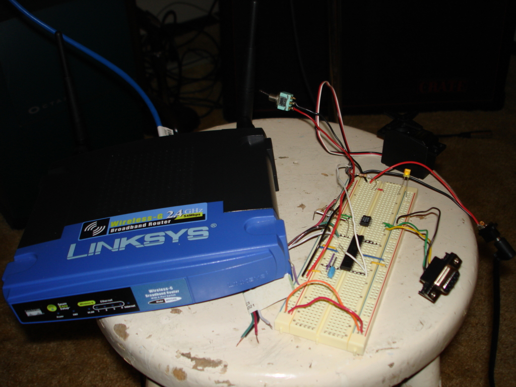
Here's the Linksys router running OpenWRT firmware. I installed my Naken Web webserver on here with a plugin that communicates over a UART to the Atmel chip using a plugin I wrote for the server. I have a DS275 and a 9 pin serial port connector since I originally tested it with a PC. I disconnected this chip and soldered wires to the motherboard of the Linksys and plugged them in pins 2 and 3 of the Amtel. The servo motor is hard to see, but it's sitting at the top right corner of the picture.
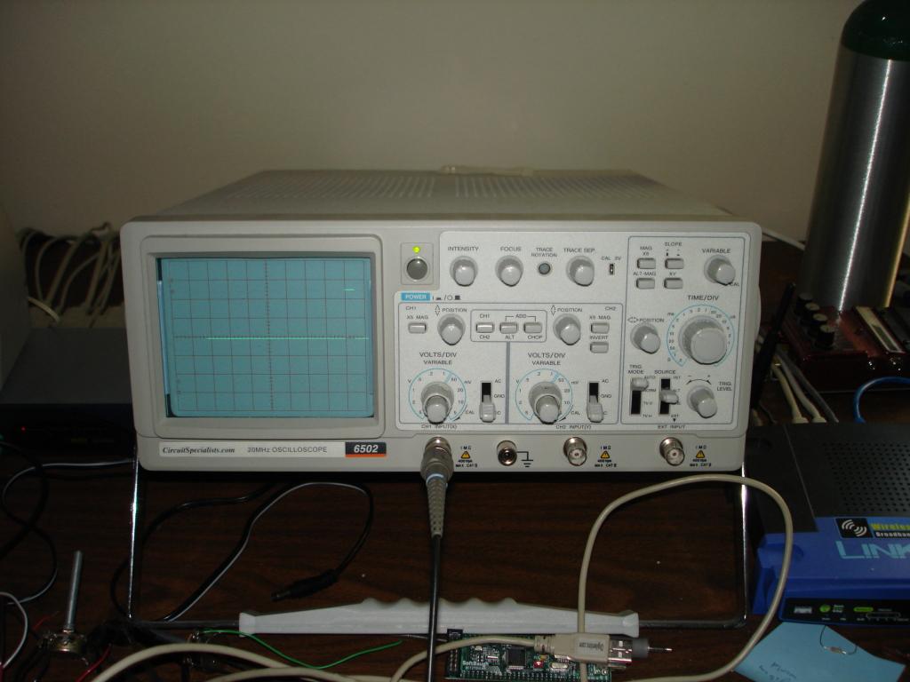
Here's a picture of the output on an oscilloscope. Each segment is 2ms in length so this is showing what the Atmel outputs when the servo is turned all the way to one direction (I forgot if it's left or right).
Download
atmel_pilot-2008-08-20.tar.gz
atmel_pilot-2008-08-20.zip
Copyright 1997-2026 - Michael Kohn
