MENSCH Microcomputer LED Blink
Posted: March 17, 2017
Updated: April 1, 2017
Introduction
I was recently contacted by The Western Design Center to see if I wanted a preview of their new MENSCH Microcomputer to try out, so who am I to say no to something like that :). So yesterday I got the board out of the package and wrote a simple LED blinking program. I figured I'd post some source code and some tips for anyone else wanting to get started with this board.
This page is still a work in progress so if something doesn't make sense or needs more explanation please send me an email and I will write more.
Related Projects @mikekohn.net
| 6502: | W65C265SXB Projects, C64 Java, Atari Java, Apple IIgs Java, Tape Data Recorder, PANCAKE-ROM, Apple IIe Robot, W65C832 |
So the first program (shown in the video below) is just a simple LED blink. The board has 8 LEDs connected to port 7 so it's a pretty simple program to set PD7 to scroll the LEDs back and forth. The source code is here:
The code assembles with naken_asm with the following on the command-line: naken_asm -l -I /path/to/naken_asm/include/65c816 mensch_blink.asm
To hook up the MENSCH Microcomputer to my laptop I used an Adafruit USB to TTL Serial Cable as shown in the picture below.
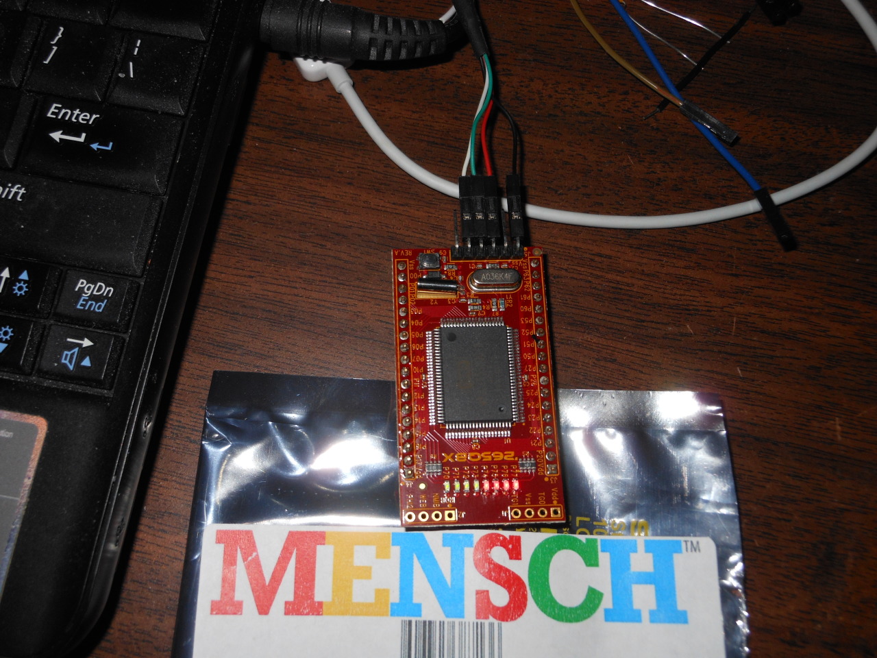
From this picture the pin on the far right is pin 1 and is hooked up to the GND (black) wire of the cable. +5v is red and is connected to pin 3, TX (green) is hooked up to pin 4, and RX (white) is connected to pin 5.
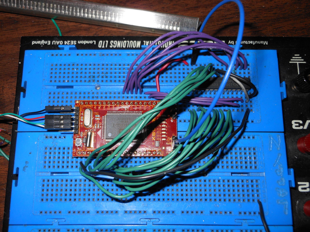
Update April 1, 2017: The picture above shows the MENSCH board in a breadboard hooked up to a CY7C199-35PC 32k SRAM chip that I got from Jameco. Pins 2 to 17 on the J4 connector of the MENSCH are A15 to A0 (the address bus) so to connect the MENSCH to the SRAM pins A14 to A0 are connected to pins A14 to A0 on the SRAM chip (all green wires). Pin A15 of the MENSCH is left unconnected. Pins 2 to 9 on the J3 connector of the MENSCH are D0 to D7 (the databus) and are connected to IO0 to IO7 of the SRAM chip (all purple wires). Since the SRAM chip is the only chip on the data/address bus, the /OE and /CE pins of the SRAM chip are connected directly to ground (grey wire and one black wire). The /WE pin of the SRAM chip is hooked up to the WEB pin on the MENSCH board. The WEB pin isn't a part of the board's J3 or J4 connector, but instead is on the J2 connector which means either a wire needs to be soldered here or a header needs to be soldered on. The WEB pin on my circuit is connected to /WE of the SRAM by a blue wire. Clicking on the image will give a higher resolution image that should help show where the wires go.
I would highly recommend hooking up an SRAM chip to this board. The first 512 bytes of RAM in the MENSCH board is pointed to by some of the interrupt vectors and could be used by the built in ROM monitor.
The video above shows how to use Joe Davisson's EasySXB to load the hex file into the MENSCH computer. Since the .org of the blinking firmware (set inside the source code above) is 0xc0, to get the program to run simply put 0xc0 in the address box and press the JML button. https://youtu.be/VX9gKZkqpps
Here's the MENSCH Microcomputer hooked up to the SRAM chip running the same program, but loaded into address 0x1000 instead of 0xc0: https://youtu.be/Ri98V-ArU1I
Copyright 1997-2026 - Michael Kohn
