Winbond W25Q128JV Flash Memory
Posted: December 25, 2020
Introduction
SparkFun was selling a breakout board for the Winbond W25Q128JV 128Mbit flash memory chip, so I grabbed one to write some simple code for it incase I needed it sometime. I started out with a MSP430G2553 microcontroller but also wrote some code in Python for the Raspberry Pi. I posted all the code below incase anyone wants it. The MSP430 code assembles with naken_asm.
More recently I used this same flash chip for an FPGA project: W65C832 (32 bit 6502).
For a deeper explanation of the Winbond flash, a friend of mine did an extensive explanation: here.
Pictures
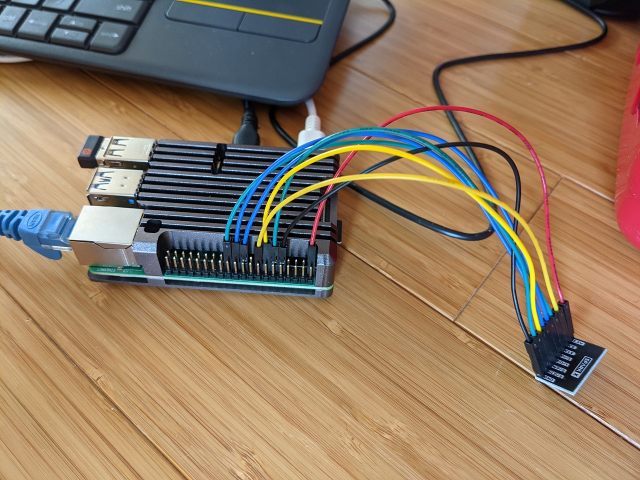
Here's a picture of the breakout board connected to a Raspberry Pi 4. Unfortunately I didn't have more colors for the 8 wires, but red/black are 3.3v and ground, blue is data in / out (MISO->DO, MOSI->DI), far left green is clock, yellow is chip select, the other green is winbond reset, and the other yellow is write protect.
Explanation
I started with the MSP430G2553 code by copying the source code from an earlier MSP430 / Ethernet project. All the ethernet code was deleted and the Winbond code was added. The concept is pretty simple: for read / writes / erases, a 1 byte command code is passed along with 3 bytes in big endian format for address of the area affected. Before writing to an area, a sector (or block) erase has to be done first (setting all bytes in the area to 0xff). I believe writing to flash can only flip bits to 0 so if the sector erase is left out, the data written could look corrupted if any bits need to be changed from 0 to 1.
Data is sent to the chip over SPI with 2 extra signals: /RESET and /WP (write protect). I use the /RESET signal on both the RPI 4 and the MSP430 by setting it low, using a delay, and then setting it back high. I tried the system without connecting the reset pin and it didn't work, so it seems it is needed. /WP is set to low so that data can be written to flash.
For the Raspberry Pi code, I decided to use Python. The gpiozero and spidev modules are used for the I/O (reset, WP, and SPI chip select) and the SPI data. Calls to spi.xfer2() read / write data from Winbond chip. To use gpiozero / spidev the modules have to be installed and the Raspberry Pi has to be configured to enable SPI:
sudo apt-get install raspi-config
sudo apt install python3-gpiozero
pip3 install spidev
sudo raspi-config
To read 4 bytes from flash memory at address 0x000000, SPI is sent 8 bytes of 0x03 for the command "read from flash", 3 bytes of the address, and 4 bytes to hold the data returned back:
spi_cs.off()
data = spi.xfer2([ 0x03, 0x00, 0x00, 0x00,  0x00, 0x00, 0x00, 0x00 ])
spi_cs.on()
Since SPI reads and writes from the bus the same time, for every byte sent there is one byte returned. The first four bytes return 0 since the Winbond is reading in a command, but for the last 4 dummy bytes sent to the Winbond, it returns data starting at location 0:
data = [0, 0, 0, 0, 77, 255, 255, 255]
The above data returned shows 77 (the letter M, since that's what I set earlier with the MSP430 code) and three 255's since those locations were unprogrammed. If I had wanted to read 2 bytes starting at address 0x000050, the SPI data sent would have been
spi_cs.off()
data = spi.xfer2([ 0x03, 0x00, 0x00, 0x50,  0x00, 0x00 ])
spi_cs.on()
Source code
https://github.com/mikeakohn/small_projects/tree/main/winbond_w25q128jv
Copyright 1997-2026 - Michael Kohn
