Analog Calculator
July 8, 2026
Introduction
This is a proof of concept of an analog calculator. While a typical computer uses hardcoded transistors as logic gates to add up binary numbers, the idea here is to use opamps to sum or subtract voltages. There was also an attempt here to create an analog memory cell, but it ended up being pretty clunky.
The first step in this project was to find an appropriate microcontoller to take user input, output the appropriate voltages into some opamps, and read the new voltages back. While doomscrolling on LinkedIn one day, I saw that Microchip was selling a cheap ~$10 board (dsPIC33AK512MPS506) which appeared to be a dsPIC33 on steroids. Seemed like the perfect chip, but it appears they are sold out, and as of this writing are still sold out. I ended up with the Microchip Curiosity Nano dsPIC33CK64MC105 instead. Still dsPIC33 but with the original core CPU.
Normally I only program microcontrollers in assembly language, but since most people seem to use C/C++ for projects like this I decided to write the code in Java (AnalogCalculator.java). Java Grinder is used to compile the Java .class files into assembly languge and naken_asm is used to assemble it into a .hex file. The Curiosity Nano shows up on Linux as a regular filesystem so flashing the chip only requires copying the .hex file to the directory which it was mounted on. No extra software or IDE was needed to do this project.
The concept of an analog calculator sounds kind of pointless, but in the world AI, maybe it could be used to emulate human emotions and emotional memory where things aren't so digital in nature.
Components Used
- Microchip Curiosity Nano dsPIC33CK64MC105
- MCP4921 SPI DAC
- MCP607 and MCP6022 opamps
- TS12A4515 electronic switch
Curiosity Nano
The Curiosity Nano ended up being the perfect devkit for this project. The feature of the dsPIC33 on this board that made it a better choice than other chips I had was the 12 bit ADC converters. Other chips in my collection had 10 bit ADCs that wouldn't have been enough. Possibly one of the MSP430 boards I have had 12 bit ADCs but this board also fit in a breadboard. Plus it was cheap. It also gave me an excuse to mess with dsPIC33 again.
A nice feature of the Curiosity Nano is the USB connection to the computer has both a built in debugger and a UART. Less cables is less clutter. In this project the UART is used as input from the user to know which numbers to add/sub and which operation to use. It's also used to read/store values in the analog memory.
There was already some support for dsPIC33 in Java Grinder, so I just had to add a little more (ADC, UART, etc) for this chip. Unfortunately, due to do the harvard architecture (separate instructions to read from flash) it made a couple things impossible. Using a String constant for example was a complexity because of this. Was tempting to add some extra API calls to read from flash, some other chips could use that too, but didn't feel like doing that now. The ADC and UART code here is all done in hardware, but I decided to implement the SPI in Java code.
Another example of dsPIC33 code in Java is dsPIC Mandelbrots which take advantage of the DSP features of the chip.
Pictures
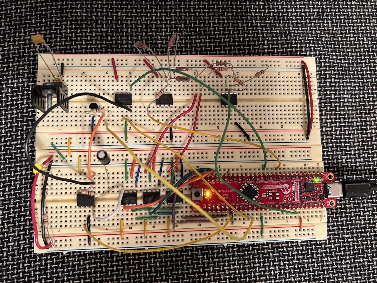
Above is completed project. The red board is the Curiosity Nano. The 3 microchips to the left of the board are the MCP4921 DAC chips. To the far left is a TS12A4515 electronic switch connected to resistor / capacitor used for the analog memory and the chip above that is another TS12A4515 used to disconnect the ADC from the memory circuit. To the upper right are the opamps used to do subtraction (left) and addition (right).
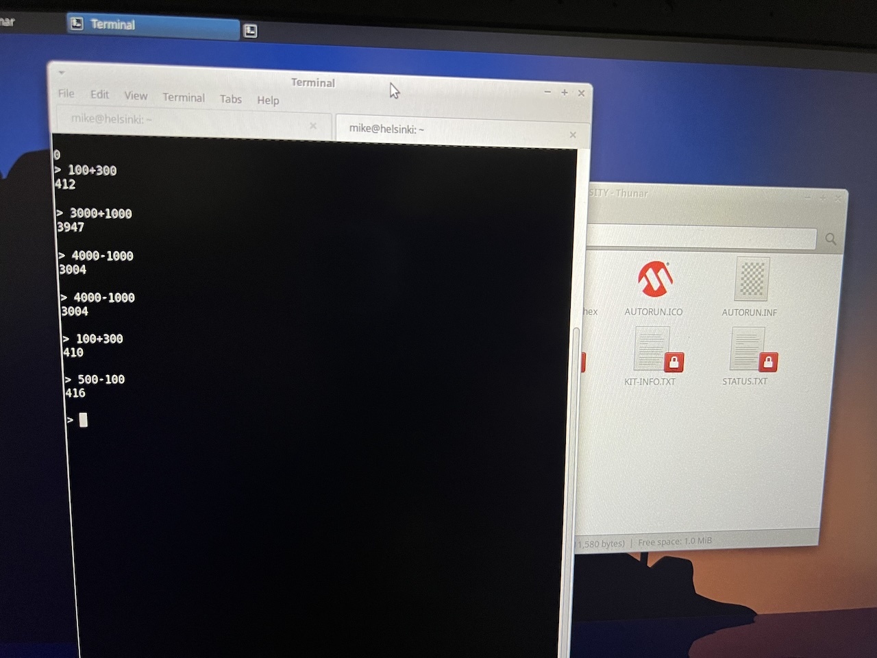
Above shows Minicom with different addition / subtraction values.
Details
A typical CPU does addition and subtraction on numbers digitally using logic gates. To do addition 2 inputs an XOR gate is used to decide if adding the values is 0 or 1 and an AND gate is used to decide if there is a carry bit. An example of that can be seen in this half adder made from transistors.
In this experiment, the numbers that are to be added or subtracted are first turned into voltages using a DAC (digital to analog converter) chip. The voltages are then fed into 2 separate opamps, one that adds the voltages together and outputs that new voltage and another that subtracts the voltages and outputs a new voltage. So for the summing opamp, if 1 input has a voltage of 1 volt and the other is 1.5 volts, the output is 2.5 volts. The two DACs used here are 12 bit, so they can represent a number between 0 and 4095 as a voltage between 0 and 3.3v. The outputs of the opamps are fed back into the microcontroller's 12 bit ADC (analog to digital converter) so the voltages (0 to 3.3v) are converted back into number between 0 and 4095.
The DAC chip used here is an MCP4921, which is an SPI based device. There are 3 DACs in this project, 2 of them are used for add/sub and 1 of them is used for an analog memory experiment.
The dsPIC33 on the board is configured to have a UART which becomes the user interface to the calculator. The only software that needs to be installed on the computer talk to the calculator software is Minicom. To make connecting things easier, a really nice feature of the Curiosity Nano board is the USB connection is used both for flashing files / debugging and the chip's UART.
Output
The outputs for add/sub varies between runs and for the different opamp types. Opamps tend to have an output voltage that sits between the Vdd voltage and the Vss voltage (the rails), but won't quite hit those voltages. So in this circuit where the Vdd is 3.3v and Vss is 0v, it will never output either 0v or 3.3v. There are however opamps that are rail-to-rail and can output those voltages.
The first opamp tested in this circuit was the MCP607 which appears to be rail-to-rail on the output, but not the input. The second is the MCP6022 which is fully rail-to-rail.
With MCP607:
> 3000+1000
3932
> 500+10
514
> 10+30
42
> 5+10
17
> 1000-400
600
> 3000-10
2946
> 50-10
40
> 0+0
5
> 4095+0
3839
With MCP6022:
> 3000+1000
3948
> 500+10
525
> 10+30
55
> 5+10
29
> 1000-400
617
> 3000-10
2987
> 50-10
54
> 0+0
26
> 4095+0
3954
The numbers are sometimes a bit off, not sure if that's due to the opamps used or possibly inaccurate resistors or possibly even the way the ADC code was written. Probably with some tweaks it could be more accurate, but I have other projects to work on. Maybe could be revisited later.
Memory Cell
As far as circuitry goes, this was probably the most complex part. A typical DRAM (dynamic RAM) memory cell consists of a capacitor and a transistor. If the value of the bit is supposed to be a 1, the capacitor is charged and to set the value to 0, the capacitor is discharged. Due to the nature of a capacitor, if the value is 1 then it will need to be refreshed multiple times a second by reading the value and writing it back to the capacitor.
The circuitry here has an extra complexity since the charge stored in the capacitor has to be a specific voltage (depending on its value from 0 to 4095) and is read back with an ADC.
I had a really hard time with this and didn't get it fully working. I tried doing the circuit a few different ways. It started with just a simple MOSFET to try to control when the capacitor could be charged or discharged into the ADC. It ends up that the body diode would cause the capacitor to discharge, so I tried a trick where an extra MOSFET is hooked up backwards, but that had issues too. I ended up with some analog switches, TI's TS12A4515, which appeared to work fine when not hooked up to the rest of the circuitry, but when in the full circuit, the capacitor would just drain.
The software to deal with the memory used one of the dsPIC33's timers to call a function periodically which would read the current value from the capacitor and then charge it back up.
Source Code
AnalogCalculator.java
Copyright 1997-2026 - Michael Kohn
