Binary Clock w/ WWVB Radio Sync
Posted: March 17, 2010
Introduction
This is simply a binary clock run on an Atmel ATMega168 chip. It displays the hour with 5 red LED's in binary format, the second counter blinks in the middle with a green LED, and the minutes are displayed with 6 red LED's. There are no controls to set the time. Instead it uses a C-Max CMMR-6P-60 to get it's time from a WWVB radio station that broadcasts an atomic clock sync'd time and date once a minute in a binary-like format.
Pictures
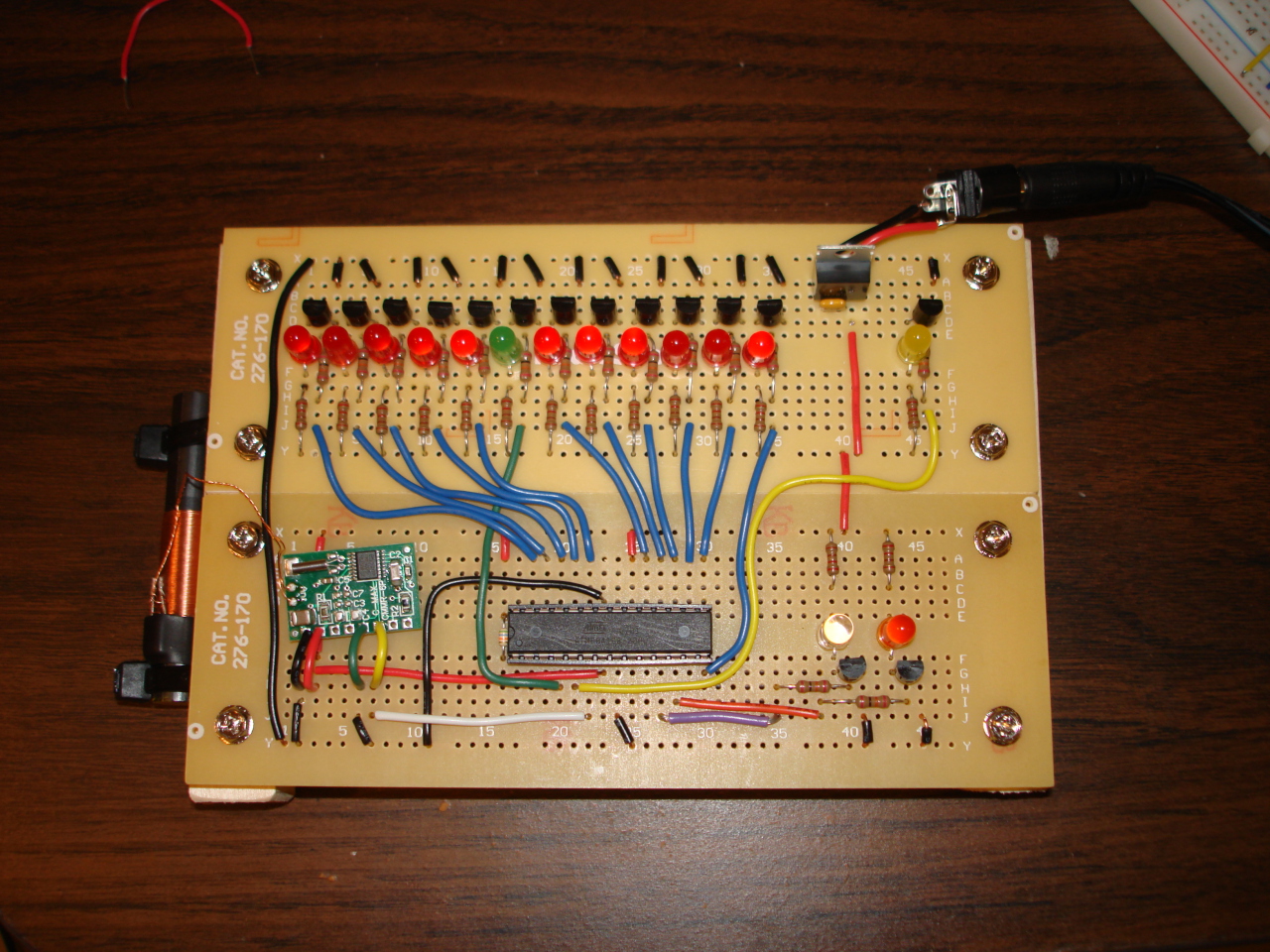
Here's the completed circuit (minus some bypass capacitors and antenna that I added later). The top row shows minutes/seconds/hours, the yellow LED in the upper right turns off when the radio signal is low, and the purple and amber LED's at the bottom right are both on for marker, amber for 0, and purple for a 1. The C-Max radio module is the green board on the far left.
Explanation
So this project is pretty much two parts. The first part is simply a clock with binary output. So basically there is a timer interrupt that fires 160 times a second. For the first 80 cycles the green LED in the middle is on and the last 80 cycles it's off. There are 3 registers to keep track of hour, minute, and second. After 60 blinks of the green LED, the minute register increments by 1 and after 60 increments of the minute register, the hour increments by 1. The hour register is written to PORTC and the minute register to PORTB.
The second part is the AM radio tuned to 60kHz to pick up the time. So I originally wanted to design my own radio so I looked up some radio circuits online to see basically how it's done and came to the conclusion I needed a 1.5mH tuning coil and 4.6908nF of capacitors (using the formula F = 1/(2*pi*sqrt(L*C))). So I was looking all over the Internet for this coil but couldn't find the thing anywhere.. not Digikey, not Mouser, not Jameco, and not with Google. So finally I put something in Digikey's search engine (can't remember what) and the C-Max CMMR-6P-60 module comes up with the right tuning coil. Clicking on C-Max brought up a whole bunch of tuning coils so I bought a couple coils so I could make my own radio (plus some capacitors to make the 4.6908nF by putting them in parallel) and the C-Max module incase it all went bad. So anyway it all went bad :). I think due to the fact that these capacitors were not very accurate, I couldn't tune the radio to the correct frequency.
So I took the C-Max module and conncted 5v to it and put the output on my oscilloscope and saw exactly the time/date data I was looking for. The output was 5v except when a bit of information started it would drop to 0v for 0.2s, 0.5s, or 0.8s depending on if it was a 0, 1, or marker. I have a video of the scope showing this that I was going to put on YouTube, but I can't stand when people write ugly comments on my videos so I think I will refrain from using that service from now on. So anyway I connected the C-Max to an input pin on the micro and added code so that every interrupt it checks the state of this pin. When the pin is low, the yellow LED at the top right will turn off, otherwise it stays on. The purple on the amber LED's on the bottom right are debug LED's that:
- If the number of interrupts which the C-Max signal was low was less than 40 (32 interrupts is 0.2 seconds) then it's a zero and only the amber LED is on.
- If the number of interrupts which the C-Max signal was low was less than 88 (80 interrupts is 0.5 seconds) then it's a one and only the purple LED is on.
- If the number of interrupts which the C-Max signal was low was less than 136 (128 interrupts is 0.8 seconds) then it's a marker and both LED's are on.
- Otherwise it's an error and both LED's are off.
So unless I'm reading this wrong, according to the WWVB spec, 2 markers in a row signal the start of a minute (plus 1 second). So after double markers the firmware shifts in bits into the hour holding register. After the next marker it shifts in bits into the minute holding register. When the next double marker is hit it can set the time.
So problems I had with the C-Max... reception seems to vary a lot depending on where I am in my house and how I position the clock. When the C-Max alone is hooked up to the scope I get absolutely perfect reception. In the circuit, the yellow light was pretty erratic showing unclean radio reception. When I put the scope back on the C-Max's output, reception got a little bit better. When I put the scope on the voltage regulator's output (testing to see if I had a clean signal from the regulator) reception became perfect again. I added two wires to the antenna out part of the C-Max and it seemed to help a little, but still not as clean as when the regulator was hooked up to the scope.
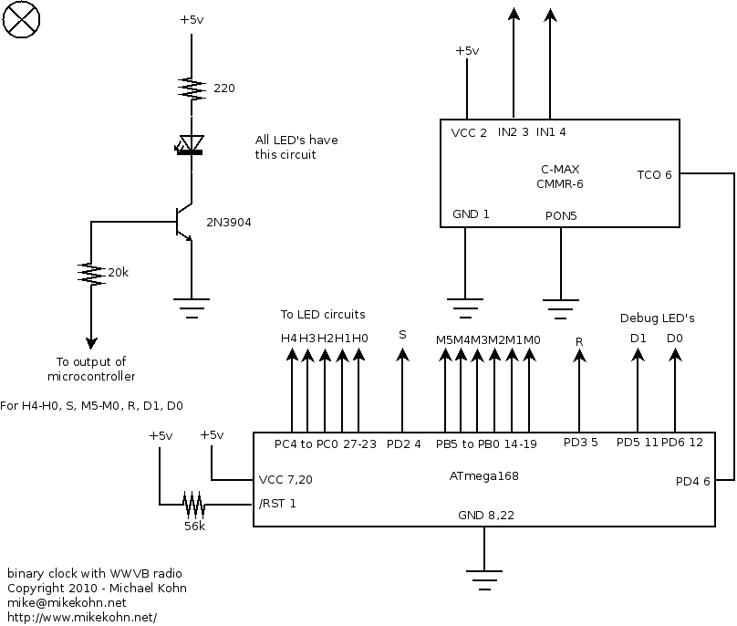
Schematic
Download
binary_clock.asm
Copyright 1997-2026 - Michael Kohn
