Fish Tank Pump Control
Posted: November 16, 2011
Introduction
A coworker friend of mine aquired a float switch and wanted a little circuit to control a heater and pump in his fish tank with the float switch. So I agreed to build a little circuit with firmware for him as long as he dealt with the 120VAC side of it (if anyone needs to be electricuted with 120VAC it's definitely him :). So this circuit controls 120VAC through a Panasonic JVN1A relay. The relay is turned on and off through an Atmel ATtiny13 micocontroller. The algorithm goes as follows: If the micro detects that pin PB3 (which has an internal pull-up to high) goes low (the float switch closed) for approximately 10 seconds, the relay will close the circuit on the 120VAC side which will allow the heater and pump to turn on. If at any time PB3 goes high again, the relay will immediately open. While the relay is open (the 120VAC side should be off) the debug LED will blink) and when the relay is closed (the pump should be on) the LED is solid.
So Mike bought a 120VAC junction box and 4 sockets. So his part of the circuit will be to connect the relay to an electrical cable that goes in the wall through the relay to the 4 sockets which he will connect his pump and heater to. To power my part of the circuit he will use a USB wall charger and a spliced USB cord which should give him the 5v needed to drive the micro. I'll post pics or links to him on that later :).
Pictures
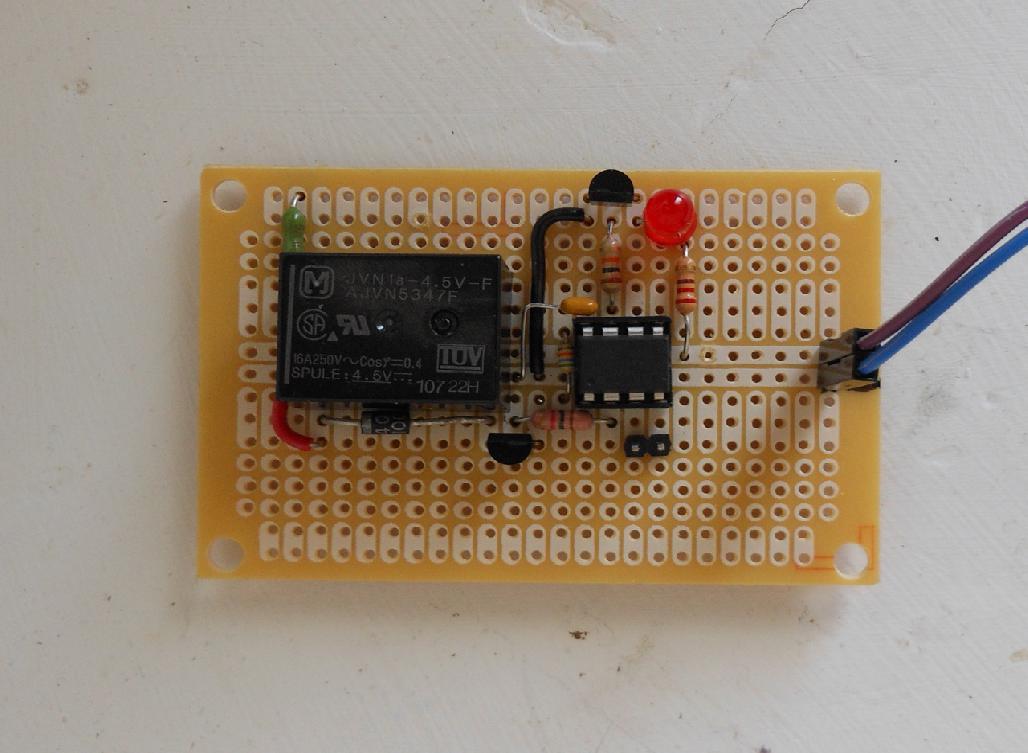
Here's the circuit board.
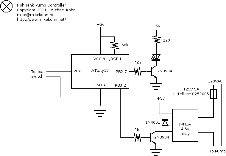
And here's the schematic...
Source code
fish_tank_pump_control.asm
Copyright 1997-2026 - Michael Kohn
