MSP430 Talking Alarm Clock Thermometer
Posted: September 1, 2011
Introduction
Here is a talking alarm clock / thermometer using an msp430g2452 chip for the MCU, a DS18B20 for the thermometer, a DS1305 for the real time clock chip, an SD card to hold sound samples, and a MCP4921 DAC for outputting sound. To program the chip I used the spy-by-wire interface of the MSP430 Launchpad without a chip installed and for the devkit I used my own assembler: naken_asm.Related Projects @mikekohn.net
| Thermometers: | Thermometers, Clock Thermometer, Bluetooth Thermometer, MSP430 DCO, E-Ink Thermometer |
Pictures

This is the board all soldered together. I left three open headers on this board so the Launchpad could again be hooked up to do Spy-By-Wire programming of the chip.
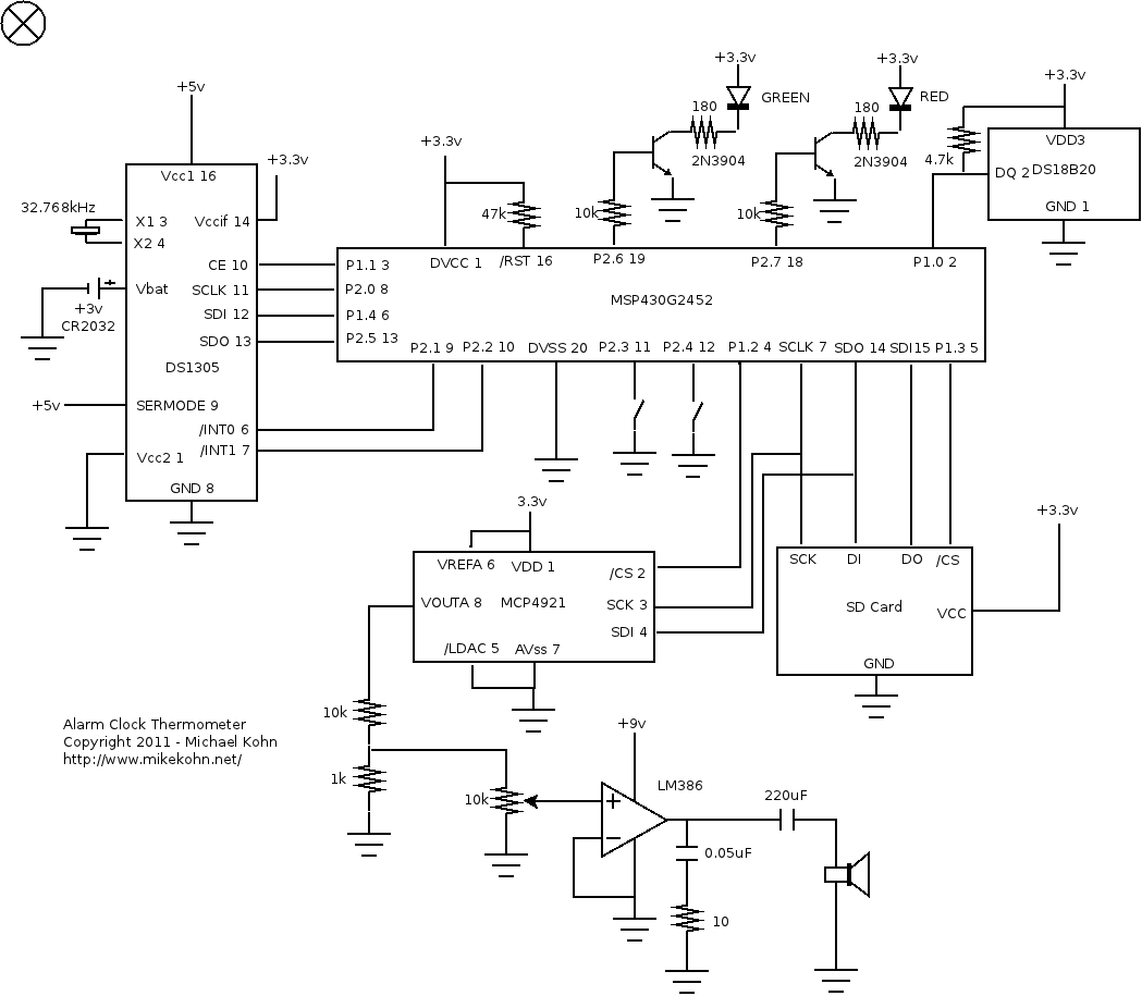
Schematic of the circuit.
Video
A video of the clock circuit working. https://youtu.be/G60Y2kAVpt0
MSP430G2452
I originally started out with the MSP430G2231 that came with my TI Launchpad kit, but when I realized I needed more pins, I switched to the MSPG2452. So I was having some stability issues I think. After I got the DS18B20 chip working I programmed the chip to speak the temperature, but when I added a few other lines of code that had nothing to do with reading from the SD card or temperature, the chip started playing the sound all distorted. I dropped the internal oscillator down a level and it started playing sound properly again. I'm thinking the problem was with the DCO so I tried putting a 16MHz crystal on XIN, XOUT. After screwing with trying to kick the crystal into running, I finally realized this chip doesn't support external crystals at this speed. The upside is I did end up needing the extra 2 pins. I was having trouble having the RTC on the SPI bus with the SD card so I ended up making a software SPI for RTC chip which used up 3 more pins.
SD Card
I used a 2GB microSD card for this. I'm actually currently only using about 4MB for the sound samples, but 2GB seems to be the smallest I could find. Anything 4GB or bigger would have required more code. I pretty much did the bare minimum here to get this card working and other cards may not work (for example if they expect the block size to be bigger than 512 bytes by default). Easy to fix, but I don't really feel the need to add the extra code.
So the code to read off the card is pretty easy, but at the same time kind of a bitch. The cards can be really picky about stuff. I've found that if a CMD17 is requested to read a block that even if chip select is disabled on the SD card, if another device is reading on the bus, the SD card will increment the pointer to the next byte needed to be read of the card, and those bytes will be lost. I compensate for it I wrote each sample to the card twice. I was originally going to do a software SPI on the DAC (and even had that part working) so it wouldn't interfere with the SD card, but in the end I decided by DAC / SD card hack would be better. Probably the more proper thing to do would be to let the SD card code sit outside the interrupt routine and buffer around 16 bytes and use a software SPI on the DAC. I could have gotten better sample rates with that. Anyway...
So I had already done an SD card / DAC sound player with my previous Atmel SD / MMC sound project so I pretty much just copied what I did there. I wanted to play my sound data at 11kHz, but I ran into the issue that after requesting a block of data from the card, the 0xfe token seemed to take around 39 tries. So 39 * 8 = 312 ticks of the SPI clock which is probably much closer to 600 to 1000 cpu cycles. Some clicky noises let me know I was overrunning the 1454 cycle interrupt routine.
I sometimes get asked if I had to implement a FAT filesystem to do this project. The answer is no. Just because an SD card is being used doesn't mean data has to be stored in FAT, ext2, or any other known filesystem. I simply used the first two blocks on the card (1024 bytes) to hold indexes to the sound data. For example the first 100 indexes on the card are the address of the sounds "zero", "one", "two", etc. So if I want to know where the sound sample is that says "fifty", I take 50 * 4 (since indexes are 4 bytes). and read 4 bytes from the SD card at address 200. Then I skip to that location in the card and read blocks of data until I read an end of sound sample 16 bit word (0xffff).
MCP4921
This is a really nice DAC chip I've used on several projects already. It's quite simple to hook up and use. The chip takes 16 bits over the SPI bus per sample where the first 4 bits are command data and the last 12 bits are sample data. For me the command bits are always 0011 (0x3).
DS18B20
I used this thermometer on my Atmel thermometer project a year or so ago. Actually, I used a DS18S20 on that one, but the code is pretty much the same. Anyway, for that project I used a series of interrupts like a state machine to get fairly accurate timings on the 1-wire bus to the thermometer. Unfortunately, as easy as it was to write that code, it doesn't read back so clearly. On this project I decided instead to make the code more "linear" so it reads a lot easier. To try and get fairly accurate timings I still used the timer interrupt, but instead as more of a signal system. For example, the write 1 function will set the bus low, set the timer to interrupt after 960 cycles (@16MHz this should be 60uS), sets the count of the timer to 0, sets r11 to 0, and loops around itself until r11 is equal to 1. When the timer interrupt fires, all it does is set r11 to 1.
The sequence of commands I send to / from the DS18B20 is a little different
than what the datasheet recommends. I can't remember if I got this from
the DS18S20 datasheet (since I copied this sequence from my Atmel project)
or if I figured it out by playing around with it, but the sequence I used
is:
SEND INIT PULSE
READ PRESENCE PULSE
SEND SKIP ROM
SEND START CONVERT
WAIT UNTIL DS18B20 SENDS 1 ON A READ SLOT
SEND INIT PULSE
READ PRESENCE PULSE
SEND SKIP ROM
SEND READ SCRATCH PAD
READ 9 BYTES
DS1305
I'm pretty impressed with the features of this chip. It has 2 alarms, a battery backup system, a battery charger (which I didn't use), battery backed up RAM (for configuration data), and it's quite easy to program over the SPI bus. I did have some weird issues with this thing at first, but it seemed to be from sitting on the same bus as the SD card. So anyway, I made a little software SPI bus and ran the DS1305 off that and all the problems went away.
Download
clock_thermometer.asm
fahr_table.inc
There are still some bugs in this code... I was delaying to
post the code until they were fixed, but I don't have time right
now so I'm posting it as is ...
Copyright 1997-2026 - Michael Kohn
