The MSP430 DCO (And A Thermocouple)
Posted: March 14, 2015
Introduction
This project started out as a simple project to connect a thermocouple to an MSP430 so the data can be displayed on a mobile device. This ended up as more of an experiment on the MSP430G2553's digitally controlled oscillator (DCO). The problem with the DCO is it's not an accurate clock source which isn't even consistent between different chips. So my goals for this project ended up being:
- Using software on the chip itself, figure out how fast the DCO really is.
- Auto adjust baud divisor based on DCO speed.
- Create a chart of all the DCO settings (further down on this page).
- Compare difference in the DCO speed from two microcontrollers with the same part number.
- Test the DCO during a temperature change (in a freezer).
- Prove Bluetooth and BLE signals can travel through the walls a refrigerator.
I posted my source code to do the calibration at the bottom of this page. Other people may find it useful for their own projects for adjusting their baud rates based on the DCO speed.
I did another project with a similar DCO issue a few months ago: MSP430 VGA with Java. This one used an MSP430F5529 to generate a VGA signal originally with the DCO and the MSP430's built in 32.768kHz crystal calibration which did create a VGA signal, but with a ton of jitter. I ended up fixing it with a real 25MHz crystal.
Related Projects @mikekohn.net
| Thermometers: | Thermometers, Clock Thermometer, Bluetooth Thermometer, MSP430 DCO, E-Ink Thermometer |
Pictures
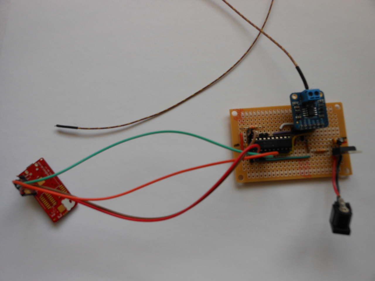
This is the thermocouple circuit with the RedBearLab BLE-Mini and a K type thermocouple.
Video
This video shows on the left an Android phone connected over Bluetooth 2.0 to my older DS18B20 Bluetooth thermometer and on the right an iPod touch connected over BLE to the newer thermocouple circuit. I put both circuits in the freezer to show that the signal is strong enough to go through a refrigerator's wall, that the DCO remains constant, and the thermocouple reacts a lot faster. https://youtu.be/EIMklPfZ-XQ
The Thermocouple
I'll start with the thermocouple since this is really the most boring part of this project. The parts I used were:
- MSP430G2553
- MAX31855 chip
- K type thermocouple
- RedBearLab BLE-Mini
The RedBearLab BLE-Mini wants a UART connection to the micro at 57600 baud which kind of becomes a challenge with the MSP430 DCO. The baud rate divisor is calculated by clock source / baud. For example: 16000000MHz / 9600 baud = 1666 (0x0682):
  mov.b #0x82, &UCA0BR0
  mov.b #0x06, &UCA0BR1
Since there is no guarantee when setting the DCO that you'll get the frequency you think you're getting, what I've done in the past while using the MSP430's UART is... well first of all I wouldn't run anything above 9600 baud. Then I would calibrate my code for the chip I'm using by looking at an output pin of on an oscilloscope, figuring out how far off my DCO is from that, and adjusting my baud rate constant for this specific chip. If I blew the chip and needed to program a new one, I had to recalibrate my code again.
I actually did think about using an Atmel ATtiny2313 (one of my other favorite chips) for this project with a 20MHz crystal or even just using a built in clock source which is still much more accurate than the DCO, but I really like the MSP430's debugging and programming tools. Also worth noting: according to the msp430x2xx user's guide, the baud rate generator can use a 32.768kHz crystal to get up to 9600 baud, but I haven't tried this yet.
The video above shows this circuit connected over BLE to an iPod touch next to my older thermometer project connected with Bluetooth 2.0. I put both in the freezer proving that the Bluetooth and BLE signals are strong enough to go through my refrigerator walls and that the the DCO appears to be stable during this temperature change. Also, it's interesting to note how much faster the thermocouple reacted to the temperature change vs. the DS18B20.
The DCO
In order to figure out the speed of the DCO in software I connected a 32.768kHz crystal to Xin/Xout of my MSP430. I set up Timer A and Timer B so that Timer A interrupts every 512 cycles and gets its clock source from the DCO. Timer B interrupts every 32768 cycles and gets its clock source from the 32768 Hz crystal. Therefore Timer B should interrupt once a second and tell how many DCO interrupts there were in that interval. Multiplying the number of DCO interrupts by 512 (aka, binary shift left by 9) should tell how many CPU ticks there were, maybe off by 511 cycles or so.
I wrote some code that would do this multiplication saving the result into 4 bytes of memory and then dividing this number by the baud rate I want. In the thermocouple circut I did this at the top of the program once.
In order to set the DCO speed, there are two constants I use: DCO_x (DCO speed) and RSEL_x (range select):
  ;; Set MCLK to 16 MHz with DCO
  mov.b #DCO_4, &DCOCTL
  mov.b #RSEL_15, &BCSCTL1
  mov.b #0, &BCSCTL2
There is also a modulator selection, which gives a frequency between two DCO frequencies. For example in my case where RSEL=15 / DCO=4 I get 14.754MHz and RSEL=15 / DCO=5 I get 15.981MHz. Using the modulator (a value between 0 and 32) I should be able to get some frequencies in between DCO_4 and DCO_5. I've never used this setting before.
So next I took the thermocouple source code and stripped it down so it was just the DCO calibration code. I programmed the chip to cycle through all DCO/RSEL combinations that it could (some ended up not working because the clock speed was too low to generate an accurate baud rate and I ended up with baud barf) and output the frequency results over UART. A Python script collects all the data and builds an HTML table which I posted below:
DCO_0 DCO_1 DCO_2 DCO_3 DCO_4 DCO_5 DCO_6 DCO_7
RSEL_0 - 0.096MHz 0.102MHz 0.110MHz 0.119MHz 0.130MHz 0.142MHz 0.157MHz
RSEL_1 0.112MHz 0.119MHz 0.127MHz 0.137MHz 0.148MHz 0.161MHz 0.177MHz 0.196MHz
RSEL_2 0.155MHz 0.165MHz 0.176MHz 0.189MHz 0.205MHz 0.223MHz 0.245MHz 0.271MHz
RSEL_3 0.219MHz 0.233MHz 0.249MHz 0.268MHz 0.290MHz 0.315MHz 0.346MHz 0.383MHz
RSEL_4 0.300MHz 0.319MHz 0.342MHz 0.367MHz 0.396MHz 0.432MHz 0.473MHz 0.524MHz
RSEL_5 0.428MHz 0.456MHz 0.487MHz 0.523MHz 0.566MHz 0.615MHz 0.674MHz 0.745MHz
RSEL_6 0.588MHz 0.626MHz 0.669MHz 0.718MHz 0.775MHz 0.843MHz 0.924MHz 1.021MHz
RSEL_7 0.834MHz 0.886MHz 0.946MHz 1.016MHz 1.096MHz 1.190MHz 1.303MHz 1.440MHz
RSEL_8 1.181MHz 1.255MHz 1.339MHz 1.436MHz 1.549MHz 1.680MHz 1.838MHz 2.031MHz
RSEL_9 1.710MHz 1.815MHz 1.935MHz 2.074MHz 2.233MHz 2.421MHz 2.646MHz 2.919MHz
RSEL_10 2.459MHz 2.607MHz 2.776MHz 2.971MHz 3.195MHz 3.459MHz 3.779MHz 4.165MHz
RSEL_11 3.061MHz 3.250MHz 3.464MHz 3.714MHz 4.004MHz 4.338MHz 4.742MHz 5.256MHz
RSEL_12 4.191MHz 4.441MHz 4.727MHz 5.066MHz 5.468MHz 5.930MHz 6.460MHz 7.100MHz
RSEL_13 5.833MHz 6.169MHz 6.538MHz 6.963MHz 7.478MHz 8.118MHz 8.911MHz 9.891MHz
RSEL_14 8.422MHz 8.944MHz 9.543MHz 10.217MHz 11.008MHz 11.895MHz 12.920MHz 14.140MHz
RSEL_15 11.744MHz 12.369MHz 13.048MHz 13.813MHz 14.754MHz 15.981MHz 17.551MHz 19.405MHz
I ran the exact same firmware on another MSP430G2553 chip and got these quite different results:
DCO_0 DCO_1 DCO_2 DCO_3 DCO_4 DCO_5 DCO_6 DCO_7
RSEL_0 - - - - - 0.126MHz 0.139MHz 0.154MHz
RSEL_1 - - 0.124MHz 0.133MHz 0.144MHz 0.157MHz 0.172MHz 0.191MHz
RSEL_2 0.152MHz 0.162MHz 0.173MHz 0.186MHz 0.201MHz 0.219MHz 0.240MHz 0.266MHz
RSEL_3 0.214MHz 0.228MHz 0.243MHz 0.262MHz 0.283MHz 0.308MHz 0.338MHz 0.375MHz
RSEL_4 0.296MHz 0.315MHz 0.337MHz 0.361MHz 0.391MHz 0.425MHz 0.467MHz 0.518MHz
RSEL_5 0.418MHz 0.445MHz 0.475MHz 0.511MHz 0.552MHz 0.601MHz 0.659MHz 0.729MHz
RSEL_6 0.583MHz 0.621MHz 0.664MHz 0.712MHz 0.769MHz 0.836MHz 0.915MHz 1.012MHz
RSEL_7 0.825MHz 0.878MHz 0.937MHz 1.006MHz 1.085MHz 1.180MHz 1.290MHz 1.426MHz
RSEL_8 1.175MHz 1.250MHz 1.334MHz 1.431MHz 1.543MHz 1.675MHz 1.830MHz 2.021MHz
RSEL_9 1.712MHz 1.818MHz 1.938MHz 2.077MHz 2.235MHz 2.423MHz 2.643MHz 2.915MHz
RSEL_10 2.485MHz 2.636MHz 2.806MHz 3.002MHz 3.227MHz 3.492MHz 3.807MHz 4.194MHz
RSEL_11 3.134MHz 3.326MHz 3.544MHz 3.796MHz 4.088MHz 4.425MHz 4.824MHz 5.339MHz
RSEL_12 4.279MHz 4.534MHz 4.823MHz 5.166MHz 5.573MHz 6.039MHz 6.560MHz 7.194MHz
RSEL_13 5.985MHz 6.328MHz 6.697MHz 7.122MHz 7.639MHz 8.289MHz 9.081MHz 10.065MHz
RSEL_14 8.906MHz 9.461MHz 10.076MHz 10.777MHz 11.586MHz 12.483MHz 13.490MHz 14.741MHz
RSEL_15 12.489MHz 13.126MHz 13.811MHz 14.623MHz 15.662MHz 16.993MHz 18.599MHz 20.444MHz
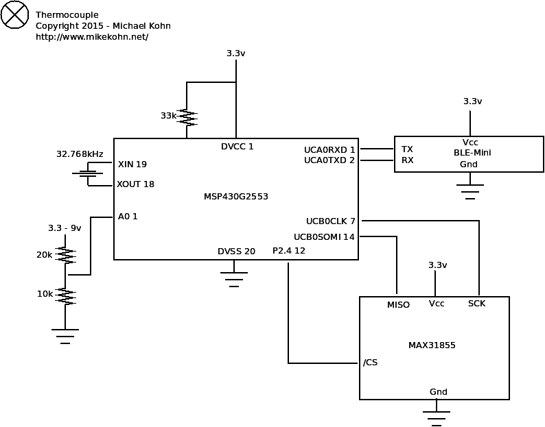
Schematic
Source code
dco_calibrate.asm
Source code assembles with naken_asm.
Copyright 1997-2026 - Michael Kohn
