MSP430 Guitar Processor
Posted: April 23, 2008
Introduction
This is a program I'm working on originally designed for the Olimex MSP430F169 evaluation board but now made to work on my own circuit which I designed based on the Olimex board. The idea here is using the Texas Instruments MSP430 to be able to plug a guitar into this device through an ADC (analog to digital converter), do some audio processing on the sound, and output it out a DAC (digital to analog converter) into a guitar amplifier. So far my goal is to turn the entire waveform into perfect square waves (which I finally have working nicely) and later into other sounds.
Update 2011-July-06: - I redid this project with an MSP430G2231, TI Launchpad, and an SPI based DAC. The new project is here.
Related Projects @mikekohn.net
| Guitar: | MSP430F169 Guitar Processor, MSP430G2231 Guitar Processor, Metal X Mod, YJM Mod, Phototransistor Preamp |
Circuit Design
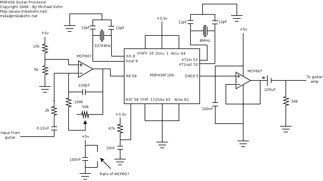
The circuit was pretty much ripped off completely from the Olimex circuit. The Olimex board is really nice, but there were a couple things that really bothered me about it that I changed in my circuit design. The first thing was the input from the guitar on the Olimex circuit is sent into an opamp that raises the voltage by 1.1 volts. This seemed really awkward to me. The ADC in the MSP430F169 has a 12 bit resolution and a vref of 2.5v. This means the sampled value is based on Vin/2.5v * 4096. Raising the voltage of the input to 1.1volts means the "center" (when there is no sound) ends up 1802 which makes the range of the input between 0 and 3604, not taking full advtange of the 12 bit resolution. And actually, I think due to inaccurate resistors, center wasn't even 1802. So the first thing I did was made the opamp raise the voltage by 1.25v using metal oxide resistors with 0.1% and 2% tolerance. When there is no sound input, the ADC reads dead on at 2047. The second thing I did is add a variable resistor to the feedback loop of the opamp so I can control the gain of the input. Very useful for my guitar with DiMarzio HS3 pickups that aren't very strong. I also used different value resistors at the input side of the opamp from the guitar since Radio Shack didn't carry the ones Olimex used :(.
The only other thing I changed was at the big-ass capacitor infront of the output jack that removes the DC component, I used a 56k ohm resistor instead of a 47k ohm resistor since that was the closest thing I had to 47k :). Also, I'm running this opamp at 5volts instead of 3.3v. I did this since my DAC is running with a Vref of 3.3v (so is the Olimex) and according to a friend of mine who is a real EE (unlike me), the output of an opamp will never reach the "rails". So I figured a 1.7v cushion would be nice to have, especially since it was almost as easy to hook it up to 5v as it is to run it at 3.3v.
Pictures
Here are pictures of the development environment:
Olimex MSP430F169 Board

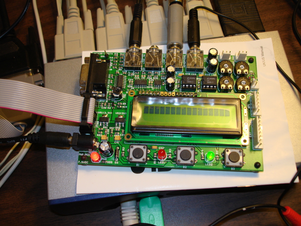
The circuit
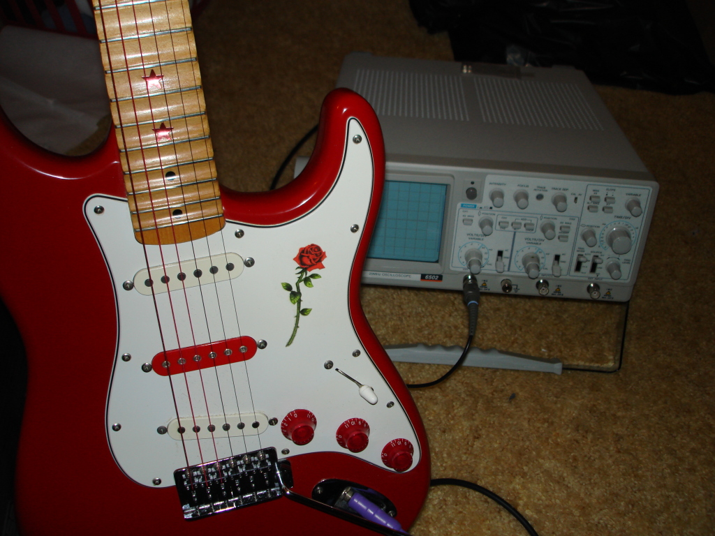
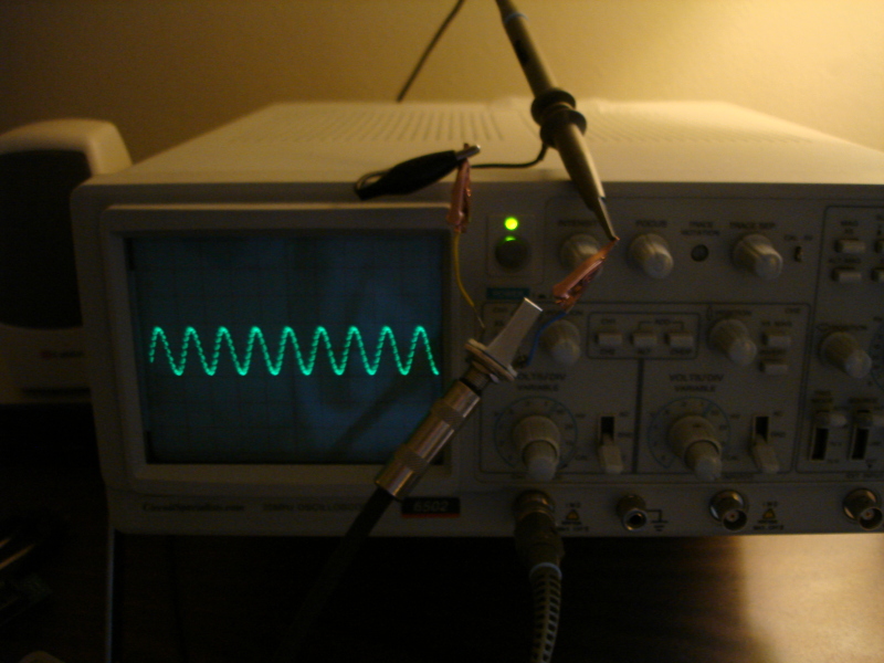
Guitar and 'scope
Schematic
I'm not sure if this schematic is complete actually. I have to look it over again.
Everything below this point is obsolete, since I created my own circuit and fixed problems. I'll post new sound files and graphs soon.
The zoomed in graphs were created with a program I wrote called wav2gif.
From the soundfile distort.ogg which is the guitar (tuned down to E flat) plugged into a Metal X (which is turned off) plugged into the MSP430 Olimex board's mic input port which is plugged into a crappy 10 watt Boss guitar amp from the Olimex line out with a Shure SM-57 microphone infront of the amp connected into a mixerboard into an SGI O2 computer.
 Low E 0.571 seconds in 1000 samples |
 High E 4.356 seconds in 1000 samples |
 Low E Power Chord 0.571 seconds in 1000 samples |
I redid the above experiment in distort2.ogg with the guitar going into the Metal X into the msp430 Olimex board directly into the mixerboard and then into the SGI O2. The lower picture is a screen shot from the SGI's sound editor software.
 Low E 0.145 seconds in 1000 samples 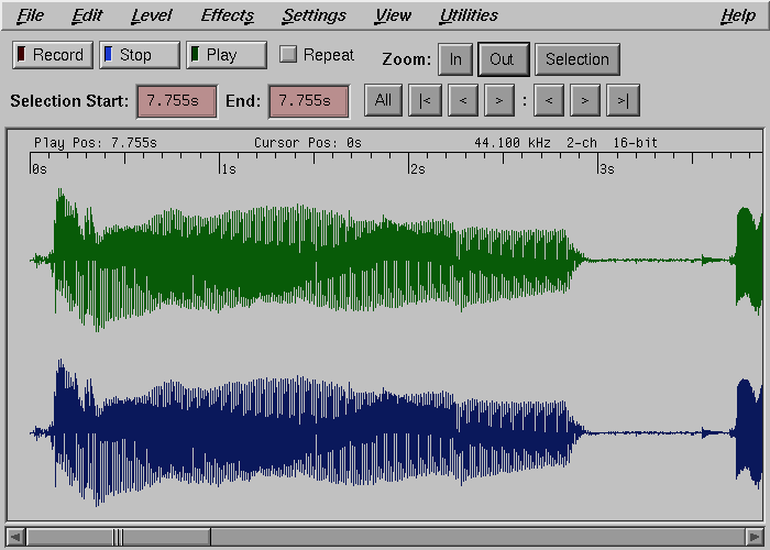 |
 High E 3.767 seconds in 1000 samples 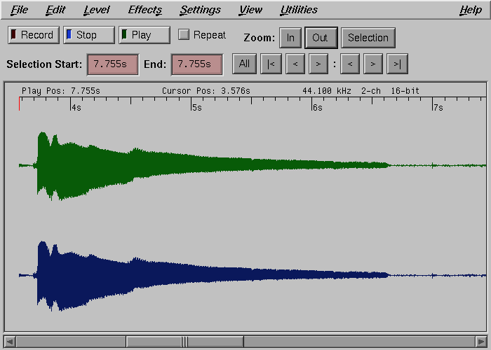 |
 Low E Power Chord 7.755 seconds in 1000 samples 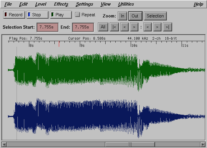 |
Something cool with these pictures.. if you take the two "High E" graphs and count the peaks, there are approximately 7. Since these were recorded at 44100 samples per second and there are 1000 samples, the frequency of the wave (computed by waves divided by seconds) is 7/(1000/44100). So the frequency of those waves are both approximately 308.7 Hz. Using information a frequence chart I found online, it shows that the high E (tuned down a 1/2 step to E-flat) is 311.13 Hz. So I'm 3 Hz off either due to approximation in the wave info from the picture or from my guitar being slightly out of tune, but other than that the graph appears to be good.. :).
Further Analysis
After fixing some bugs I fed into the system a perfect A440 wave at 8000 samples a second. Using the GNU Octave (https://www.octave.org/) Matlab clone I wrote the following code:
a=cos(2*pi*440*[0:(1/8000):10]);
ausave('a440.wav',a,8000,'short');
I outputted this wav file directly into an oscilliscope from a computer and got this picture:
I then hooked the computer's sound output into the MSP430 Olimex board and got the following output:
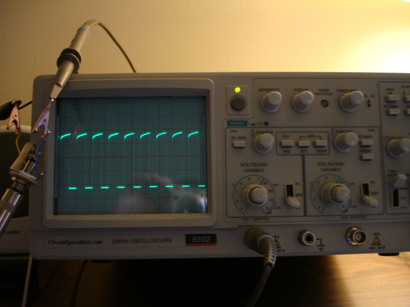
The first image shows a perfect sine wave. The second image shows I am creating square waves (except for the peaks for some reason). The 0 voltage center is off by a little bit causing the valleys of the waves to be shorter than the peaks. I think this is due to the fact that the signal is raised by 1.1volts in the Olimex board with a reference voltage of 2.5volts. Seems to me Olimex should have raised the input signal's voltage by 1.25 volts instead (2.5/2).
Copyright 1997-2026 - Michael Kohn
