Lego Data Reader
Posted: June 6, 2022
Introduction
Back in... probably the 1970's and early 1980's before disk drives were popular, people used to write computer programs on punched cards. I've heard some pretty awful horror stories of these things, being tedious to use, people dropping sets of them so they become unsorted, etc. Anyway, I thought it might be fun to recreate the concept using LEGOs.
This project is a computer program written on an 8x20 plate of LEGOs where the 8 bumps on the LEGO represent 1 byte of data. A black area is 1 and white is 0. The program is read in using an array of 8 IR sensors. The program is fed under the sensors using a servo motor. To keep as much of the project made out of LEGOs, LEGO train tracks and wheels were used to slide the program under the sensors.
The software on the LEGOs was written in 65C816 assembly language and runs on the Western Design Center's W65C265SXB board.
Below is a video, pictures, full explanation, and source code.
Related Projects @mikekohn.net
| Storage: | Tape Data Recorder, PAPER-ROM, PANCAKE-ROM, LEGO Storage |
Video
The video shows the LEGOs sliding under the sensors. At the end, when the program is fully loaded, the Western Design Center SXB board at the top runs program which blinks the LED close to the chip.
Explanation
The project starts with led_blink.asm:
.65816

.org 0x1000
  sei
  clc
  xce
  sep #0x20
  rep #0x10
main:
  lda.b #0xff
repeat:
  sta PD7
delay:
  dey
  bne delay
  eor.b #0xff
  bra repeat
The program is assembled with naken_asm using the command-line option -type bin so it can be dumped on the command line:
$ hexdump -C led_blink.bin
00000000  78 18 fb e2 20 c2 10 a9  ff 8d 23 df 88 d0 fd 49  |x... .....#....I|
00000010  ff 80 f6                                          |...|
Those 19 bytes are "written" to the 8x20 plate of LEGOs using black LEGO pieces to represent 1 while the white areas are 0.
The LEGOs
Finding the right LEGOs for this project was really kind of a pain. There are lots of (expensive) LEGO kits, but obviously no LEGO punched card kit. I got most of the pieces from the LEGO shop at the local mall and their online store "Pick A Brick" option. The selection is HUGE and it's hard to figure out what to put in their search engine to find parts. There wasn't an 8x20 board so it had to be created with four 4x5 boards. I also ended up accidentally ordering LEGOs that were light gray instead of white so they were not usable for this project.
After creating the plate with the code on it, the next step was figuring out how to slide it under some sensors. It ends up LEGO has train tracks and wheels, axels, motors, etc to go along with them. The tracks were easy to find. The rest of that, not so much. The "Pick A Brick" option didn't have any of that, unless I missed it. So the tracks came from the LEGO City Tracks set (with a lot more pieces than were needed) and the wheels and axels came from Amazon from someone selling a kit of 4 wheel / axels.
The Sensor
Pololu sells an 8 Channel Reflective Sensor Array that lines up perfectly with the bumps on the LEGOs. If the sensor is over black areas it won't reflect as much while white reflects the IR back into a phototransistor which causes the output voltage to drop. The output of the sensor goes into pins P1.0 to P1.7 of the MSP430G2553. Each pin is a different ADC channel on the microcontroller to convert the input voltage into a number. Only one channel can be read at a time so when the motor stops it cycles through all 8 channels. If the number read in is less than 0x2ff it is read back white and is considered 0, otherwise it's a 1.
I was actually a little worried that since the black areas were raised and closer to the sensor that it might reflect back more IR than the white areas despite black being less reflective, but it worked perfectly.
The Stepper
This is my first stepper motor project so I wasn't quite sure why there would need to be a whole separate stepper motor board. It seemed kind of simple to just trade off voltages across the two coils maybe similar to a brushless motor, but after dealing with the board it makes more sense now.
The motor driver used here is a SparkFun ProDriver with a Toshiba TC78H670FTG stepper motor driver chip. So it seems the chip can advance forward based on partial steps and hold the value. In this circuit P2.0 to P2.3 select the stepper mode and P2.4 / P2.5 are used for enable and standby. Tip of advice: I accidentally left the motor enabled while it wasn't moving for over an hour and dang that motor got hot.
This board is also providing the 3.3v power to the MSP430 and the Pololu reflective sensor array.
Reading Data
The sequence for the stepper motor and reading data follows the following pattern:
  call #read_sensor_byte
  call #spi_send
  mov.w #100, r15
  call #step_forward
  call #delay_200ms
The delay of 200ms isn't needed, but I added it for dramatic effect. The spi_send is more of a 2wire thing since there's no chip select and also no input. At the end the firmware will send a byte of 0x00 to let the sxb_loader.asm program running on the WDC board to know it's time to run the code that was transfered over.
Pictures
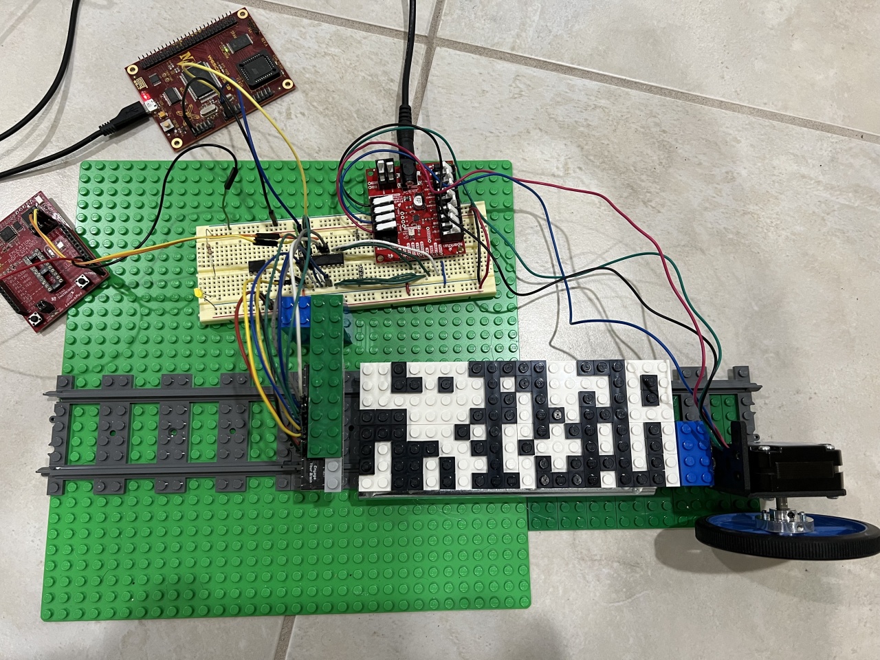
Top view of the project. The board at the top is the Western Design Center W65C265SXB board with the 65C816 based CPU. On the far left is an MSP430-EXP430G2 Launchpad board with the chip removed so it can be used as a firmware flasher and debugger for the MSP430G2553 on the breadboard. To the right of the MSP430 is a SparkFun Stepper Motor driver connected both to the MSP430G2553 and the stepper motor. Byte 0 of the program is all the way to the left in this picture and the most significant bit is towards the bottom. So the first row at the top is 0111 1000, or 0x78 in hex.
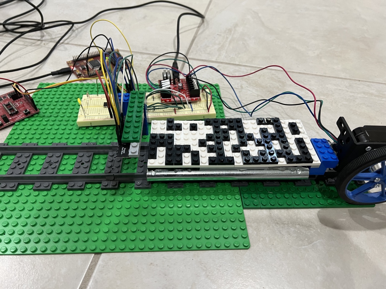
Side view of the project. Below the LEGOs board with the code is a bar of steel that I hot glued to this side of the board to balance out a weight difference due to the stepper motor not being centered. Without it the wheels were coming up off the tracks. The Pololu Reflectance Sensor is hot glued to the green strip of LEGOs at the top.
Source code
lego_reader.asm
sxb_loader.asm
led_blink.asm
Copyright 1997-2026 - Michael Kohn
