PAPER-ROM
Posted: July 10, 2013
Introduction
Here's a weird little project for recording digital data on a disk of paper and read it back with a line detecting sensor. The bits are read in one by one and sent to the computer as single bytes over an ATtiny2313's UART / RS232 similar to the same thing I did with my tape data recorder a couple years ago. I was debating whether to use an MSP430 or an AVR8. The MSP430 would have made the 16 bit calculations I did here simpler but doesn't have an accurate high speed crystal. The ATtiny2313 can take an external 20MHz resonator plus I wanted to do another project to test naken_asm with AVR8 assembly code.
Related Projects @mikekohn.net
Video
I wasn't sure what to focus on while making this video. It was neat watching the disk spin and the arm move, but it's also neat watching the letters show up on the screen so I did a little of both. Hopefully it looks okay. There are pictures of the system further down on the page. https://youtu.be/xtuXbxDowTg
Explanation
I started out with a C program (disk.c) written to run on a desktop computer that would read in a file and create a GIF image of the data so I can print it out. The disk consists of 4 tracks. Each track has a start marker which is a width of say "X". Then each bit is either 1/4 the size of X (for a 0) or 1/2 the size of X for a 1. This means the amount of data that can be stored on the disk is dependant on what the data is, but it also means that it kind of doesn't matter how dense the data is. If I want to attempt to store more data, I can make the size of the start marker thinner by changing disk.c and when the microcontroller starts reading in a new track, it should find the length of this start marker and adjust itself for the width of the bits of data.
So now that I have a disk, I needed parts to make the disk spin, the sensor arm move, and sense the black and white parts. I already had a positional servo motor (Futaba S3004) that I attached to a plastic tube to for a moveable arm. For the motor to make the disk spin at a constant rate I used a continuous rotation servo (Futaba S148) I found from Pololu. The difference between the two servos being, the positional sets its position based on a pulse between 1ms and 2ms and the continuous will spin clockwise or counter-clockwise at a rate based on a pulse between 1ms and 2ms. A 2ms pulse seems to make my disc spin at 60RPM counter-clockwise. I would have expected this servo to stop spinning at 1.5ms but around there it seemed to just spin slowly or in the opposite direction if I made the pulse thinner, so I stopped the motor by just not sending it pulses. To mount the servos in a stable structure I took a shipping box from Mouser that I had laying around from a recent shipment and cut some slots in it so the servos would slide in snug.
The IR Sensor
In order to sense if I'm over black or white I found a QTR -1RC from Pololu, which ended up being pretty simple to make work. Basically there are 3 pins here (Vcc, Gnd, OUT). Vin and Gnd should be obvious, but the OUT takes a little bit of code. The way it works is the microcontroller sets its pin to an output and goes high for around 10-15us, and then the amount of time it takes to discharge will tell if it's over black or white. So the micro's pin connected to OUT is then changed to an input and after around 195us the pin is polled. If it's pointed at black it shouldn't discharge very quickly (should read back a 1) while if it's over white it will discharge fast and a 0 is read back. I set up TIMER0 on the ATtiny2313 to count 100 ticks which at 20MHz comes out to about 5us and made a small function that returns a 0 or 1 depending on what color the sensor is over.
Reading Data
The following steps were used to read in a track:
1) Move arm to correct position (track 0 to 3) and turn on spinning servo.
2) Delay around 50ms to make sure the motor is really spun up and arm moved.
3) Read 134 black marks and record the length of the widest mark (start marker).
4) Calculate and store 1/2 start marker length (bit 1) and 1/4 this size (bit 0).
5) Read in black marks until the widest mark is detected (start marker).
6) Read in bits until start marker is seen again. Wide marks are 1 and
thin marks are 0.
7) After 8 bits are read in send a byte over the UART.
8) Move to next track and repeat 1 to 7 until all tracks are read.
The Math
In order to make sure I wasn't going to overflow two 8 bit registers combined
to make a 16 bit register, I did some measuring. First I assumed that the
disk will be spinning at 60RPM (1 revolution per second). I then got the
radius of the disk (8cm) which using 2 * pi * r gives me a circumference
of 50.27cm. So next I calculated the circumference at the center of all
tracks and came up with this:
track 0: radius = 7.5cm, circumference = 47.10cm
track 1: radius = 6.0cm, circumference = 37.68cm
track 2: radius = 4.5cm, circumference = 28.26cm
track 3: radius = 3.0cm, circumference = 18.84cm
So next I measured the width of each of the markers:
Start Marker: 1.4cm
Bit Value 1: 0.7cm
Bit Value 0: 0.35cm
Since each track has a difference circumference they are spinning at a different
speed. The speed is calculated by circumference / 1s. So track 0 would be
7.5cm/s. So now I need to know how much time the sensor will spend under
each mark at each track. To calculate that it's simply: length of mark / circumference / 1s:
; track 0 @1 RPS = 30ms, 15ms, 7ms [ 154 77 36 ]
; track 1 @1 RPS = 37ms, 19ms, 9ms [ 190 97 46 ]
; track 2 @1 RPS = 50ms, 25ms, 12ms [ 256 128 62 ]
; track 3 @1 RPS = 74ms, 37ms, 19ms [ 379 190 97 ]
The 3 numbers on the right are the number of times my function (read_sensor())
will be called to last the duration. For example, on track 0 the start
marker will be under the sensor for 30ms so during that time I should be
able to call read_sensor() around 154 times and a return value of black.
After making these calculations, I tested this and got back 157. Considering
I don't really know the disk is spinning at 60RPM and my 195us is more of
an estimate, this is pretty good :).
Pictures
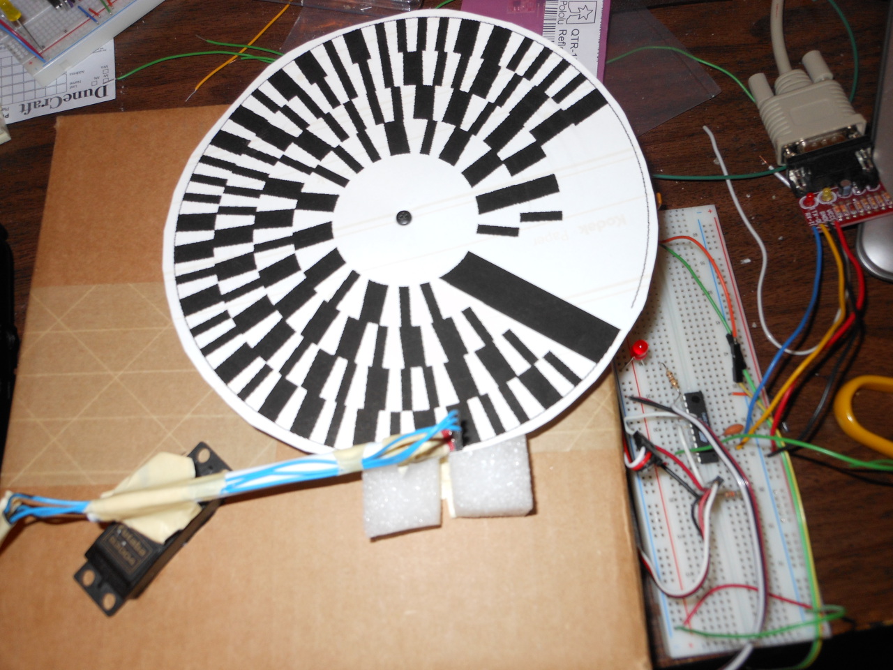
Here's the circuit board along with the Mouser box with two servos mounted in it. The arm is attached to the servo with masking tape. The LED on the board turns red every time it's above black and off when above white.
Here's the disk I generated with disk.c. This disk holds 16 bytes which say simply: "Michael Kohn...". Starting from the outside track after the start marker going counter clockwise it's SHORT LONG SHORT SHORT LONG LONG SHORT LONG: 01001101 = 0x4d = 'M'... etc etc.
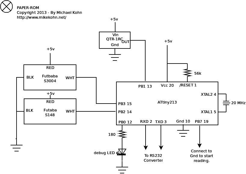
And here's the schematic...
Source code
paper_rom.asm
disk.c
Copyright 1997-2026 - Michael Kohn
