Sony SIRC Infrared Communication
Posted: January 12, 2010
Updated: February 12, 2011
Introduction
This page now serves as the home of two separate SIRC projects. The first I did back in January of 2010 where using an Atmel ATtiny2313, I created a bi-directional IR communcation using Sony's SIRC IR protocol. The second I did in September of 2011 with an MSP430G2231 and a microSD with voice sound samples so that when a remote control is pointed at the circuit, the circuit will speak the key that is being pressed. Even more recently (February 12, 2012) I added a third circuit that will send the temperature over IR using SIRC to the receiver module to speak it.
Related Projects @mikekohn.net
| Infrared: | Remote Control, IR Guitar Pickup, Sony SIRC Infrared,, R/C Propeller RPM, IR No Fly Zone, Syma Joystick, Paper ROM, Chromebook Remote, Remote Control Food, Alexa TV Remote |
Atmel ATtiny2313 Project
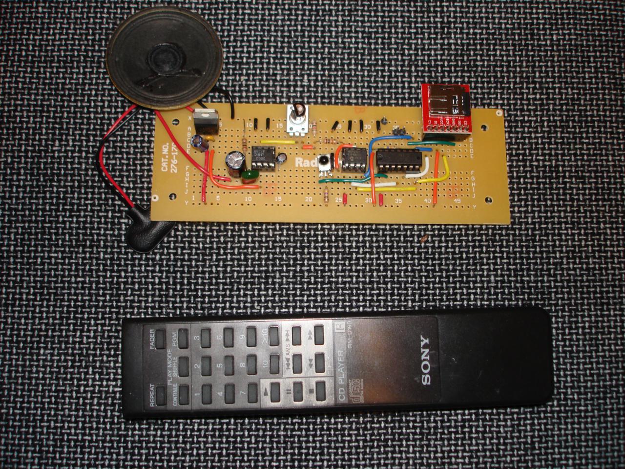
This project serves two purposes. First is to be just a simple IR receiver for Sony remote controls. I used an old Sony RM-D190 remote control from an old CD player I threw out long ago to test. When the receiver gets data over the IR, it sends it as 2 bytes over RS232 to a computer. The data will be (in 11 bit mode.. this description is breaking SIRC which should bre LSb to MSb.. can't remember if this is a typo) from MSb to LSb: 5 bits of 0, 3 bits of device, 8 bits of data packet. Or something like that. The second part of the project is to make an IR emitter transmit data when it receives information over the RS232 line.
TI MSP430 Project
I threw this one together really quick just for the heck of it. I used the microSD sound / hardware from my talking clock thermometer project. The rest was as simple as creating an interrupt routine that counts when the input to P1.0 is low so the main routine can see how long each pulse is. The main routine reads the command bits and the address bits separately into two different memory locations, checks to make the address bits are 0x11 (audio remote control.. maybe TV too?), adds 1 to the command byte so that pushing "5" on the keypad makes the voice say "5" instead of the command code of 4, and then calls the "say" routine to speak it.
Update February 12, 2012 - I made a second circuit (and updated the original MSP430 receiver circuit) that take a temperature reading from a DS18B20 thermometer chip and sends it using address of 7 in the SIRC packet and the command being the temperature in celcius. For this circuit I used a spare DS18S20 which hardware-wise is identical, but the software shifts the output value by 1 instead 4 to remove the fractional part of the temperature.
The source code below can be assembled with my naken_asm assembler.
Pictures
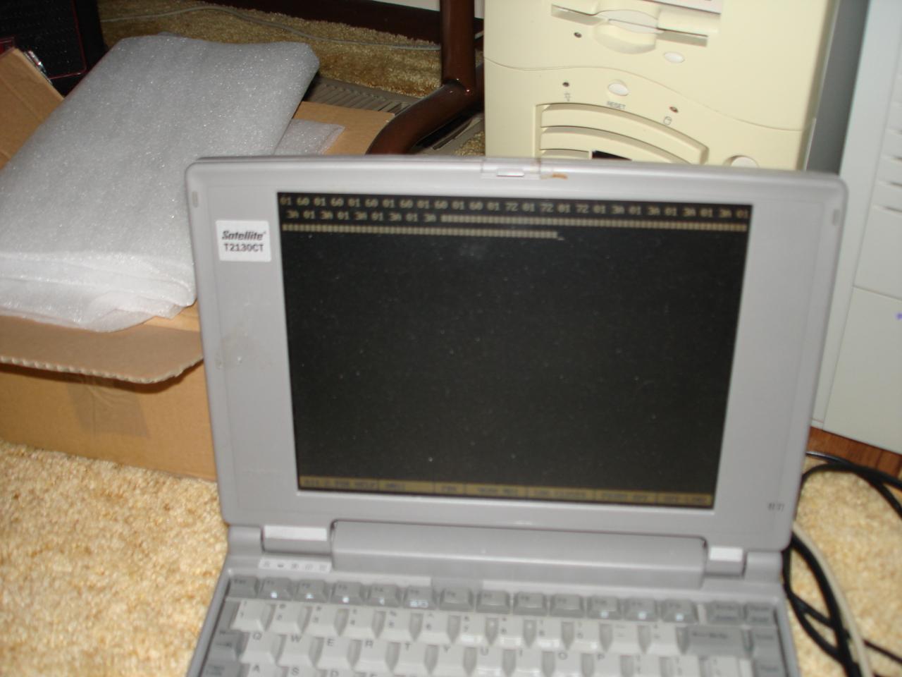
Here is an example of what the output of the chip looks like. This crappy 486 laptop is running Procomm Plus in FreeDOS and is hooked up to the circuit. When I push buttons on the remote, they are printed as hex chars (for debugging). The # marks indicated IR errors.
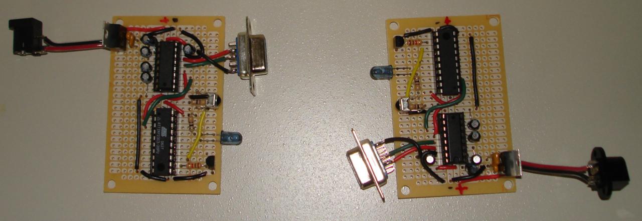
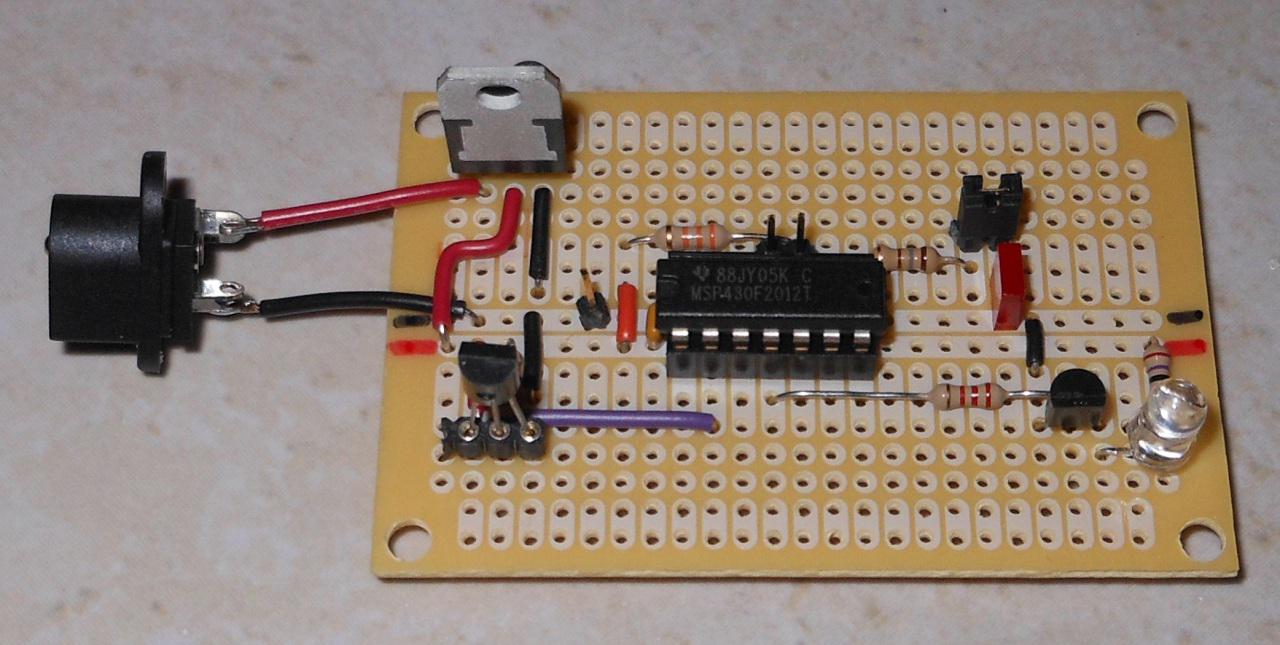
Here is the final two circuits. Using terminal programs (Picocom on Linux and Procomm Plus on FreeDOS) I can communicate between the two computers with 2 way communication over IR using these circuits.
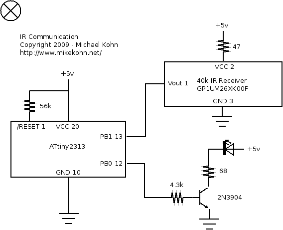
This schematic leaves out the RS232 part since it should be straight forward to add it in. I normally use DS275's to do RS232 since it's simpler, but on this circuit I used a MAX232.
The MSP430G2231 SIRC circuit.
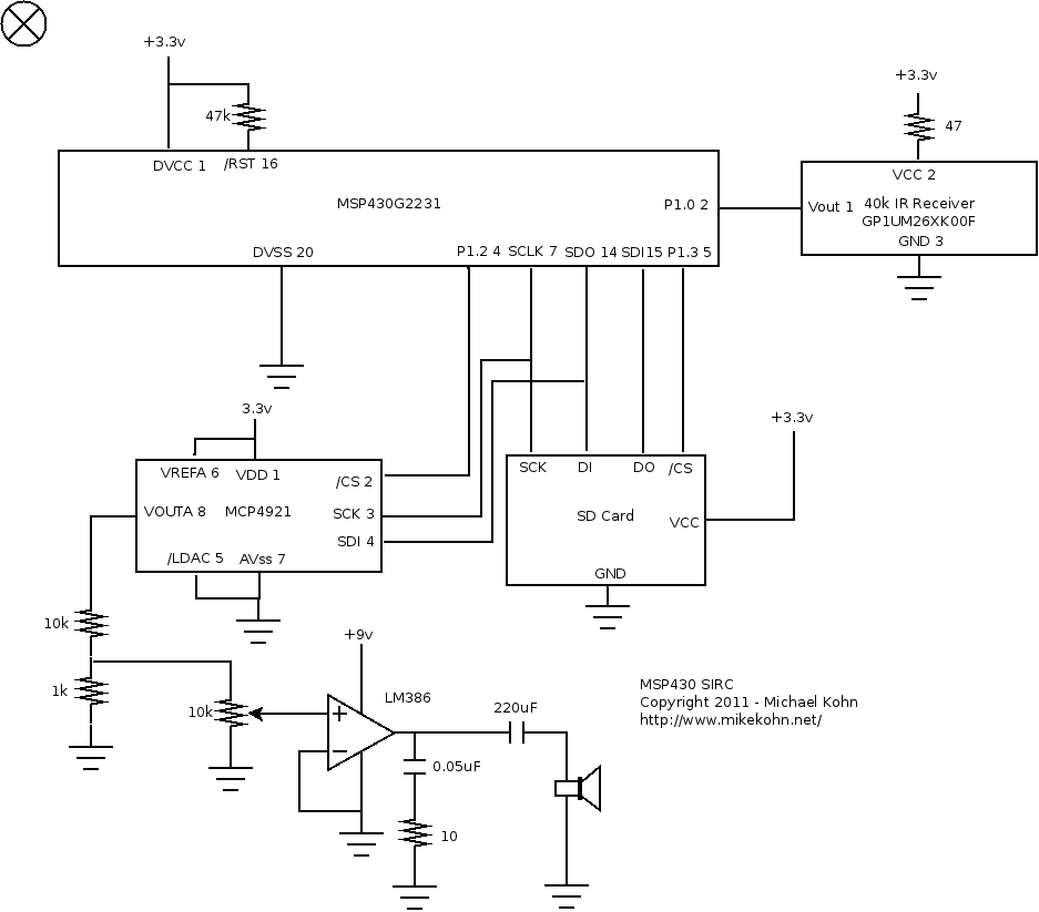
Schematic for the MSP430G2231 receiver circuit.
The MSP430F2012 SIRC transmitter circuit. This circuit has a DS18B20 (actually, in this circuit it's DS18S20) that reads the temperature and sends it to the receiver circuit.
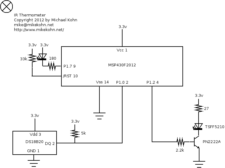
Schematic for the MSP430F2012 transmitter circuit.
Source code
ir_comm.asm (Atmel ATtiny2313 source code)
msp430_sirc.asm (MSP430G2231 receiver source code)
ir_thermometer.asm (MSP430F2012 transmitter source code)
Copyright 1997-2026 - Michael Kohn
