R/C Propeller RPM (Tachometer)
Posted: August 7, 2010
Introduction
While working on the Linksys Quadcopter project, I decided I needed to figure the speed the propellers were spinning so I could calculate thrust. I looked online for some cheap tachometers, but the ones I found required sticking a piece of reflective tape on the spinning object. Heh, that wouldn't mess up the calculation at all. Anyway, I designed and built this circuit and after taking the RPM and propeller model and plugging it into this website: www.badcock.net thrust can be pretty accurately calculated. Measuring the weight of the Linksys Quadcopter on a scale with the motors off and with the motors running full speed showed 800 grams of thrust. Finding out the RPM of the propellers and plugging in this website showed the same result.
I also ended up using this circuit on a remote controlled basla wood airplane project. Related Projects @mikekohn.net
| Infrared: | Remote Control, IR Guitar Pickup, Sony SIRC Infrared,, R/C Propeller RPM, IR No Fly Zone, Syma Joystick, Paper ROM, Chromebook Remote, Remote Control Food, Alexa TV Remote |
Explanation
The firmware on the chip is pretty simple. Since the ATiny2313 has two timer modules on it, I used the 8 bit Timer0 module simply to figure out if 1 second has passed. For the IR part, I borrowed the circuit from my R/C car drag racing christmas tree. On the circuit board is an IR emitter which is simply always on spraying IR forwards. An IR detector is connected through a transistor to the T1 pin of the micro which serves as the clock source for Timer1. After 1 second has passed, Timer1 should have a count of how many times a propeller blade has swiped across the IR system and sends this number over to a computer through RS232. The computer then takes this number and divides it by 2 (since the propeller has 2 blades) and multiplies it by 60 to get the revolutions per minute.
Pictures
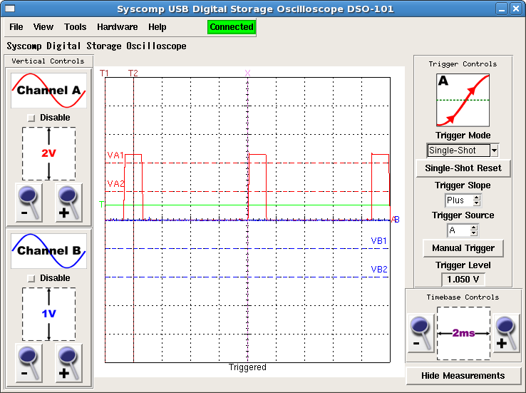
Here's a view of the output from the IR detector while running 10x3.8 propellers at almost full speed on the Linksys Copter. Originally I was calculating RPM just by the output of the IR into an oscilloscope, but after testing the IR part, I added the microcontroller which counts the IR pulses for me and outputs RPM on a computer screen.
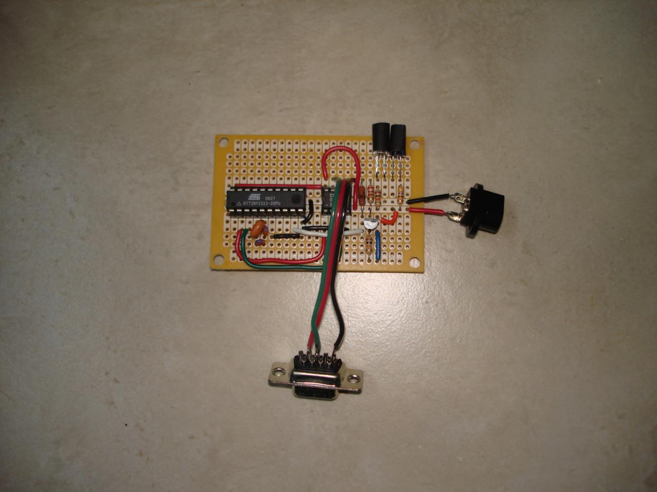
This is how the circuit board looks. At the very top right are the IR emitter and detector. I covered them with shrink tubing to stop leakage and some ambient light. The micro (on the far left is an Atmel ATtiny2313 and the chip in the middle is the unforutnately almost extinct DS275. The IR system needs to be around 3 to 6 cm from the spinning propeller in order to detect the blades.
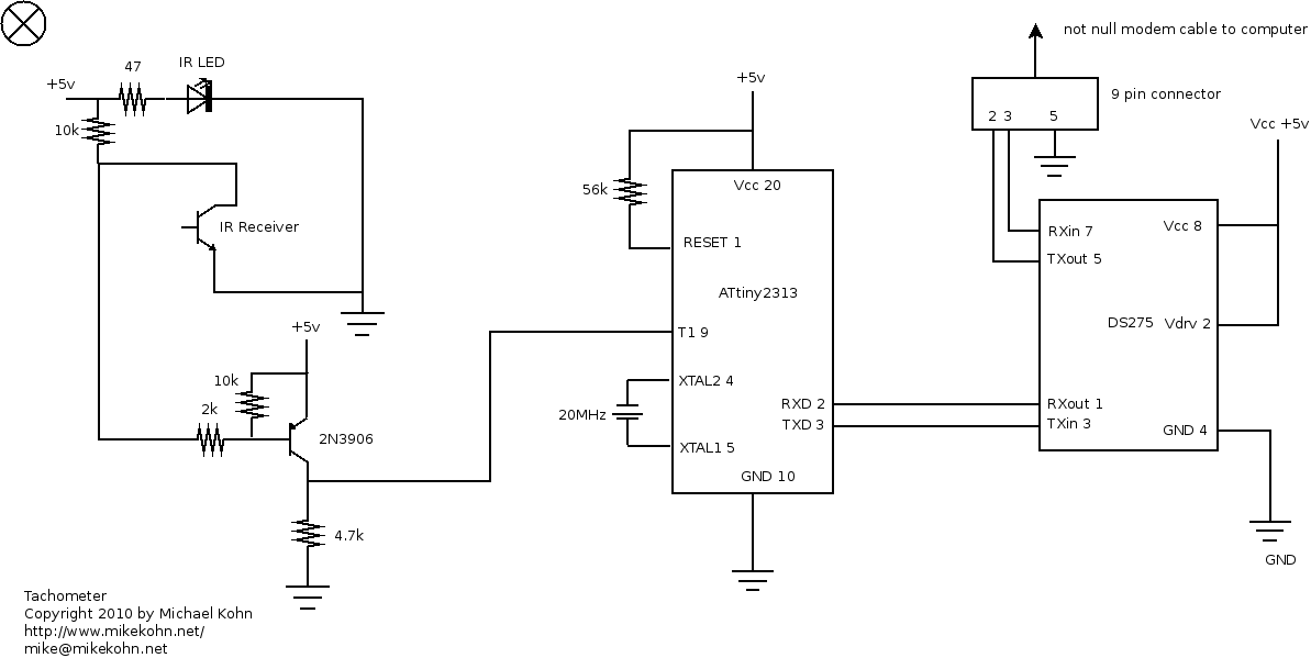
Schematic for the circuit.
Source code
tachometer.asm - ATtiny2313 firmware.
tachometer.c - Linux source to read from device.
Copyright 1997-2026 - Michael Kohn
