Drag Racing Christmas Tree For RC Cars
Posted: June 9, 2010
Updated: July 22, 2023
Introduction
This is a two part circuit for racing RC cars. The first part is a drag racing christmas tree with 3 yellow lights, a green light, and a red light at the bottom. The circuit has sensors to detect if a car crosses the starting line before the light turns green and a speaker to make 1980's car racing game sounds. The race is started with a simple push button. At the end of the drag racing track is a circuit to show which car won the race.
There are currently 3 versions of this system on this page:
- Version 1: Atmel AVR8 based with no communication (June 2010).
- Version 2: Pololu Wixels / 8051 core with built in wireless (September 2016).
- Version 3: MSP430 microcontroller / XBee communication (July 2019).
- Version 4: ESP32-C3 RISC-V with WiFi communication (July 2023).
This is one of the few projects that I actually get email about (which is kind of nice). The two questions I get asked most are if I can build these circuits for money and the second is if it would work for real cars. As far as real cars, with some modifications to circuitry that drives the lights, it should work fine as long as the outdoor light doesn't trigger the IR sensors. As far as building these for money, it's kind of not worth my time to do that. It takes a weekend to solder all these parts and I work a full time job. If at some point I could make my own printed circuit board for this, then maybe, but I don't have experience doing those. If some company wants to partner with me on building kits for this, feel free to send me an email.
All the different versions are described below along with pictures, videos, source code, and schematics.
Source code
git clone https://github.com/mikeakohn/rc_drag_racing.git
Related Projects @mikekohn.net
| RC Cars: | IR Toy Car, IR Toy Car dsPIC, Bluetooth RC Car, RC Drag Race, WiFi RC Car, Xbee RC Car, RC Food |
Version 4: ESP32
I've been posting pictures on Twitter of the progress. The circuits are pretty much done, just needs some software.
The start and end track circuits are using the Espressif ESP32-C3-DevKitM-02's. Unlike just about every other embedded project on this website, the code for this project is written in C++ instead of assembly. It was started with straight C to match the example code from Espressif, but realizing the circuitry on both the start / end tracks circuits have so much similarity, it seemed to make more sense to make a DragRace.h class that initializes all the common components and have DragRaceStart.h and DragRaceEnd.h for specific circuit. Unlike versions 1 to 3 of this project, the firmware for the start and end track is a single binary with a jumper from GPIO19 to ground to configure it as the end track. Chosing the ESP32-C3 board also makes the project a bit cheaper since these modules cost around $8 each while the MSP430/XBees would be around $30-$40 per circuit.
This system is also improved because it runs a tiny web server on the starting track ESP32-C3. This means the race can be started by a webpage on a laptop, which will also receive the timing scores when the races end. The HTML is running some Javascript which can keep track of multiple players along with their best score and rank them. At one point I was thinking of making a desktop app for it so the races could be printed out on thermal paper. I might do that later.
Above is a demonstration of the ESP32 version of the drag race circuit. The video shows a the normal operation of the timing track and also a view of the webpage that can start the race and keep track of everyone's score. There's also a demonstration of a car crossing the start line before the race starts causing the player's score to show up as "fault". If there is no laptop available, the race can still be started with a push of a button on the starting circuit. There are 4 lasers pointing at the 2 phototransistors at the start and 2 phototransistors end of the track to detect if a car is crossing the line. Each sensor has a debug LED that turns on if the beam is broken. This is needed for setting up the system so it can be seen if the LEDs are properly aligned with the sensor. YouTube: https://youtu.be/SIP3ABYVJAg
When the circuits are turned on, the end track will display 9999 on both displays, letting the user know it's not connected to the start track. There are a few glitches still in the system. When the circuits are plugged in, they are running a RTOS so they take a few seconds to start running the firmware. There's really nothing that can be done about that. The next is, I believe due to some important pin being used, the board won't start up until the reset button is pushed. I think there might be a config setting to fix it in the devkit. Also, the TX pin for the UART is the same as GPIO21, which on the starting track is the right red light. When that pin is set as a GPIO in software, the ESP32 monitor will stop working. So if the monitor is needed for debugging the start track, the code that makes that pin GPIO needs to be commented out. Also, the end track seems to sometimes not connect to the start track and I believe the start track has to be reset. Maybe that doesn't happen anymore.
The ESP32-C3 on the front track circuit is running a small webserver that understands 3 pages:
- http://192.168.1.4/ - To retrieve index.html defined in the git repo. This runs a Javascript program to control the race and could be easily changed by modifying the html before compiling.
- http://192.168.1.4/start.json - To signal the system to start a race.
- http://192.168.1.4/status.json - To request the current state of the race.
The status.json file will have the following format:
{
  "right_score": "5.37",
  "left_score": "5.68",
  "right_fault": false,
  "left_fault": false,
  "timing": false,
  "running": false
}
If running is true, it means a race is going on and timing is true only after the tree drops to "green" and the timers are both running. The C++ modules for the firmware have a design like this:
       DragRaceStart     DragRaceEnd
             |                |
             |                |
             |                |
Laptop  NetworkStart     NetworkEnd
  |          |                |
  |          |                |
  |__________|________________|
DragRaceStart runs forks out 2 threads, one for the webserver and one for the TCP server that the NetworkEnd can communicate with. If a laptop signals the race to start, it sets flags in the NetworkStart code, and the DragRaceStart module will poll for it. The NetworkEnd code has a similar design.
This circuit should be easier to put together than the previous since it requires less components. The most tedius part is cutting all the wires to solder in. The LM386 circuit is also a pain. This probably could have been done with just a transitor without the volume control. This circuit uses a board mounted speaker that I found on SparkFun's website instead of a regular speaker hot-glued to the structure. SparkFun also sells some sensors that could probably be used for the laser detection that might work and simplify the circuit. I actually got a set for this, but ended up not trying them.
I haven't decided yet if I'll draw schematics for this.
Circular Race Track
YouTube: https://youtu.be/FCKgIbiCu_U
May 14, 2025: Above is a modification to a Mini Golf project that turns it into an RC Car racing circuit. A laser detector was added to the ESP32 which is used to know if the car is breaking the start / end line. The ESP32 makes sure the car doesn't start early and times 3 laps. On this circuit, the tree is run by an ATtiny85 which receives pulses from the ESP32 to control it.
The source code for this project is in the same repo as the drag racing circuits.
Version 3: MSP430 / XBee
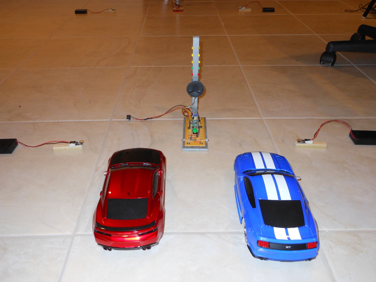
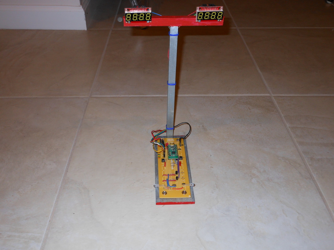
I ended up selling the Wixel version of the circuit to someone, so I decided to build a new one using MSP430 and XBee radios. It seems the lasers I used before were discontinued, so I got different lasers and hot-glued them to some wooden mounts so they were a lot easier to aim. The source code for this version is also on GitHub.
Like the Wixel circuit, I took this circuit to work to have coworkers help me make a video (shown above). YouTube: https://youtu.be/v6fWhuO8RxQ
Some interesting difference and maybe advantages for using MSP430 / XBee are that the XBee's have a very long line of site range, in some modules over 1 mile. It's also a reliable radio protocol, so when the start track sends a command to the end track, it's guaranteed to get it. The negative being there could be added latency to that.
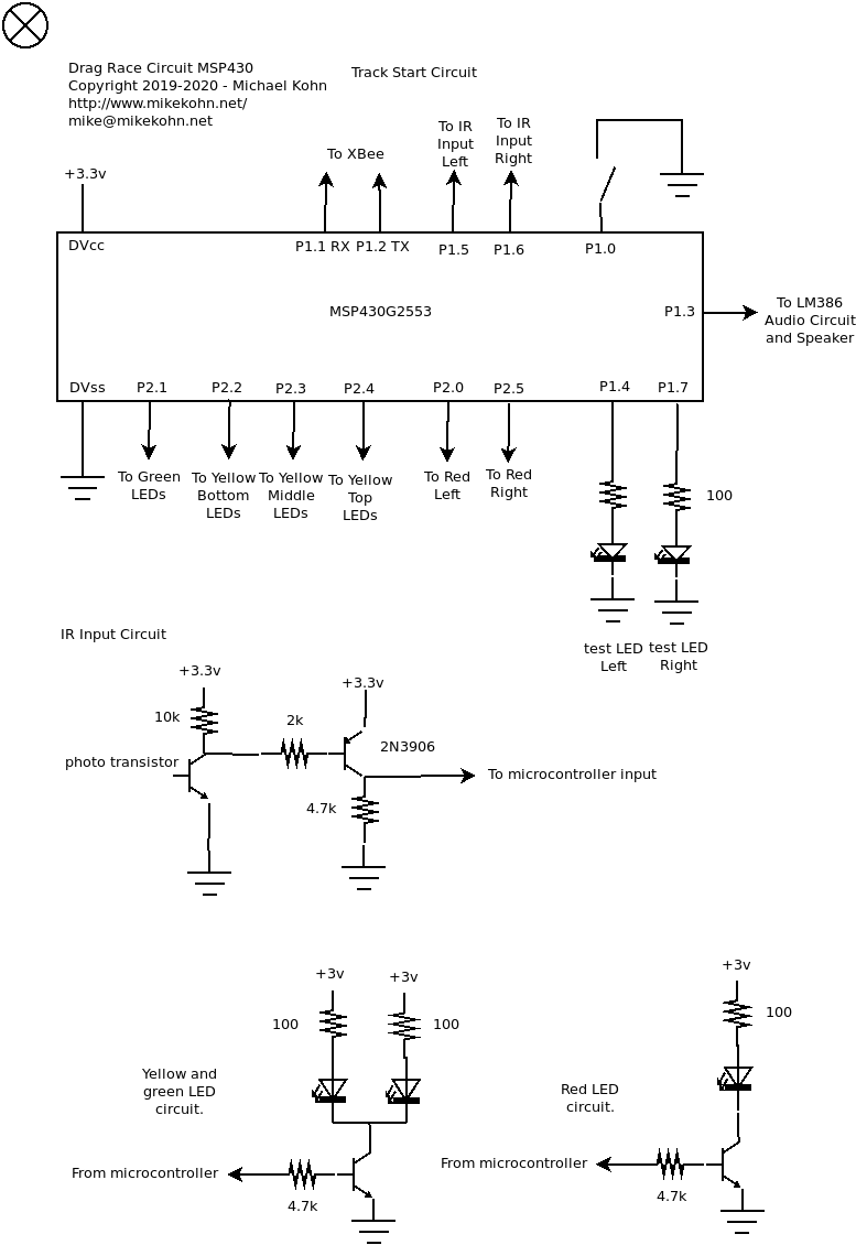
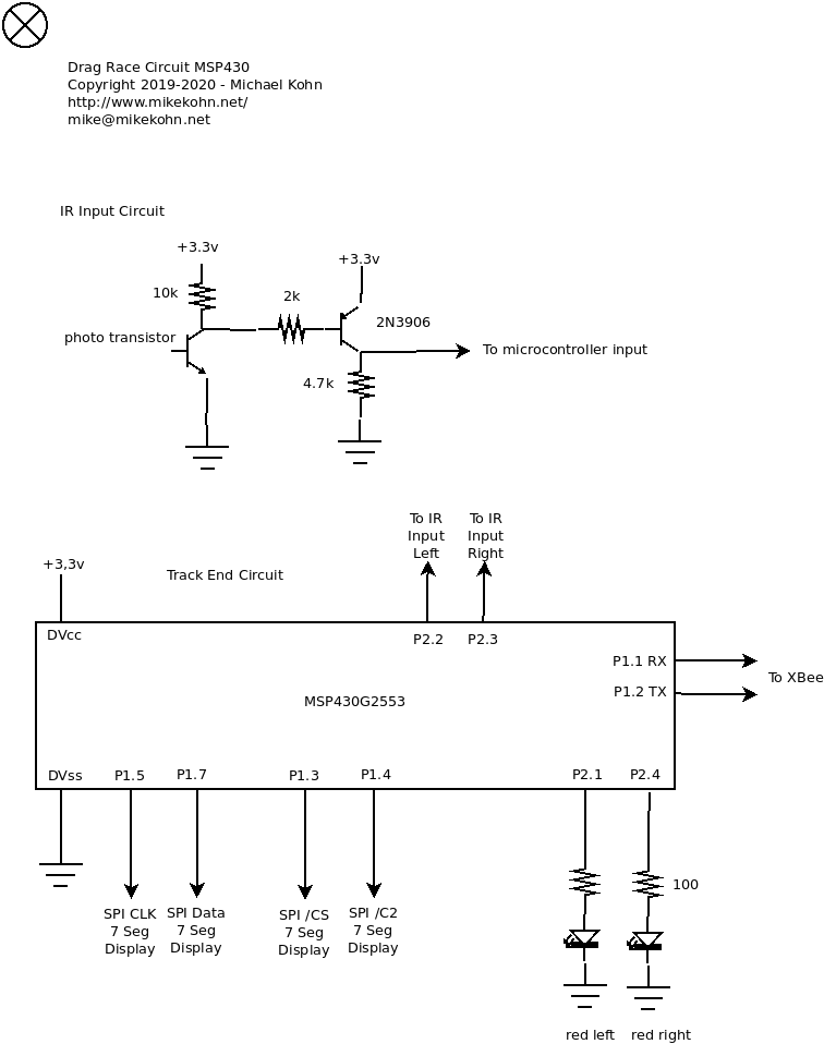
Above is the schematic for the MSP430 based circuits.
Version 2: Pololu Wixel
The second version of system is done with a pair of Wixels from Pololu. Unlike the original circuit below, the finish line circuit has two SparkFun 7-Segment Serial Displays that show how much time has elapsed since the race has started. These displays are really nice (actually felt a bit like cheating) since they have their own microcontroller to drive the LED's and just need commands sent to them over SPI (or i2c / UART).
Here's a video of the new Wixel circuits, first on my desk at home showing the circuitry works and then at work where my co-workers helped me by driving the cars. Those cars are unfortunately still very difficult to control due to the fact that pushing left / right on the steering control turns the wheels full left / right. YouTube: https://youtu.be/JwOyFHUCe60
Since the Wixels are based on the on a TI CC2511F32 microcontroller which have built in radios, the finish line circuit can be told when to reset the timers, start the timers, or clear the timers (because of a disqualification) by the starting line circuit. Also, instead of using infrared bouncing off the car to detect it crossing the starting / finish lines, for this circuit I used a 650nm Red Laser pointing into a TEPT5600 Light Sensor Transistor.
Probably the hardest part of this circuit (besides the mechanics... aiming the lasers correctly, cutting the wood, soldering all the wires to a clean length, etc) the hardest part was probably the radios. I originally just read through the datasheet and and tried to use all the default values, but I couldn't get the circuits talking. I emailed Pololu asked for help and they recommended I just convert the C code from their SDK into assembly and use that. Other than an 8051 mistake I made it worked pretty much first try. Nice to see a company that is extremely responsive and seems to care about supporting a product they make. The SDK they make actually seems pretty nice, but again I really wanted to learn 8051 assembly and test naken_asm.
One odd note about the 8051 mistake I made when converting the C code to assembly for the radios: The mistake was I pointed to the DMA configuration to the wrong part of memory by forgetting the # in the assembly instruction. When I started up this bad firmware, the netbook I was developing the code on lost contact with my 2.4GHz WiFi access point and wouldn't reconnect until I reset the device / fixed the firmware. It seems I must have flooded the same radio channel that the 802.11 WiFi was using.
Other than the obvious parts (LED, resistors, 2N3906 transistor, PC board, wood, acrylic paint), I used the following parts:
- Pololu Wixel
- SparkFun 7-Segment Serial Displays
- 650nm Red Laser
- TEPT5600 Light Sensor Transistor
- Speaker (0.5W 8ohm)
- 3xAA Battery Holder
The new Wixel based starter circuit with 2 radio controlled cars. The structure is made out of wood and painted with acrylic paints. The LED's and the speaker are attached to the wood structure with hot glue. This time I have bigger cars (Jada 1/16 scale cars) so they should be easier to control. To the left and right of the cars are the 3 AA (~4.5v) battery packs connected to the lasers that point at the photo sensors. These specific battery packs are really nice since they have an on/off switch on them.
The new end of track circuit has two 7 segment displays for a timer accurate to 1/10th of a second. The timer stops when the cars break the laser beam pointed at the photosensors. Because the displays can be controlled with SPI (as they are in this case) I was able to tie all the common signals together (data, clock, vcc, gnd) which minimized the number of wires and also makes sure they are in perfect sync. The only uncommon wires between the displays are the chip selects. So to stop a timer the only thing need to be done was to keep /CS at +Vcc for either the left or right 7 seg display. I did this by keeping the R7 register of the 8051 as a global /CS value.

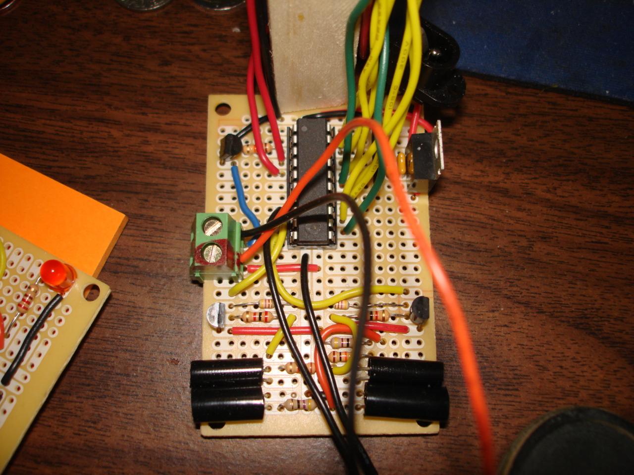
Here's a closer up view of both the starting and ending track Wixel circuits side by side.
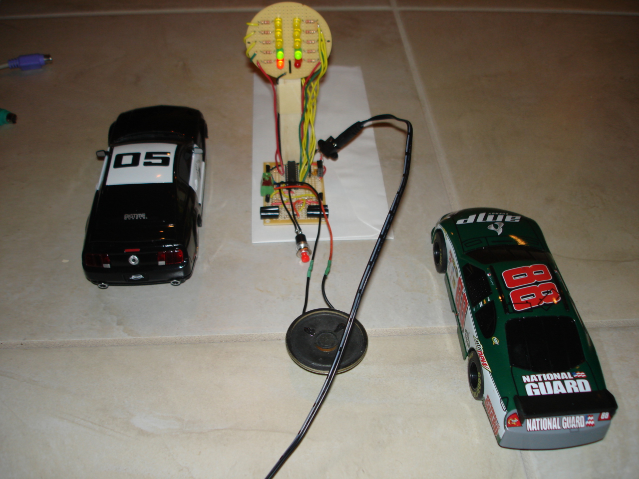
Front view of the original Atmel AVR8 starter circuit with 2 smaller radio controlled cars (I believe these are 1/24 scale). This picture shows the car on the left moving forward early and faulting, turning on a red light.
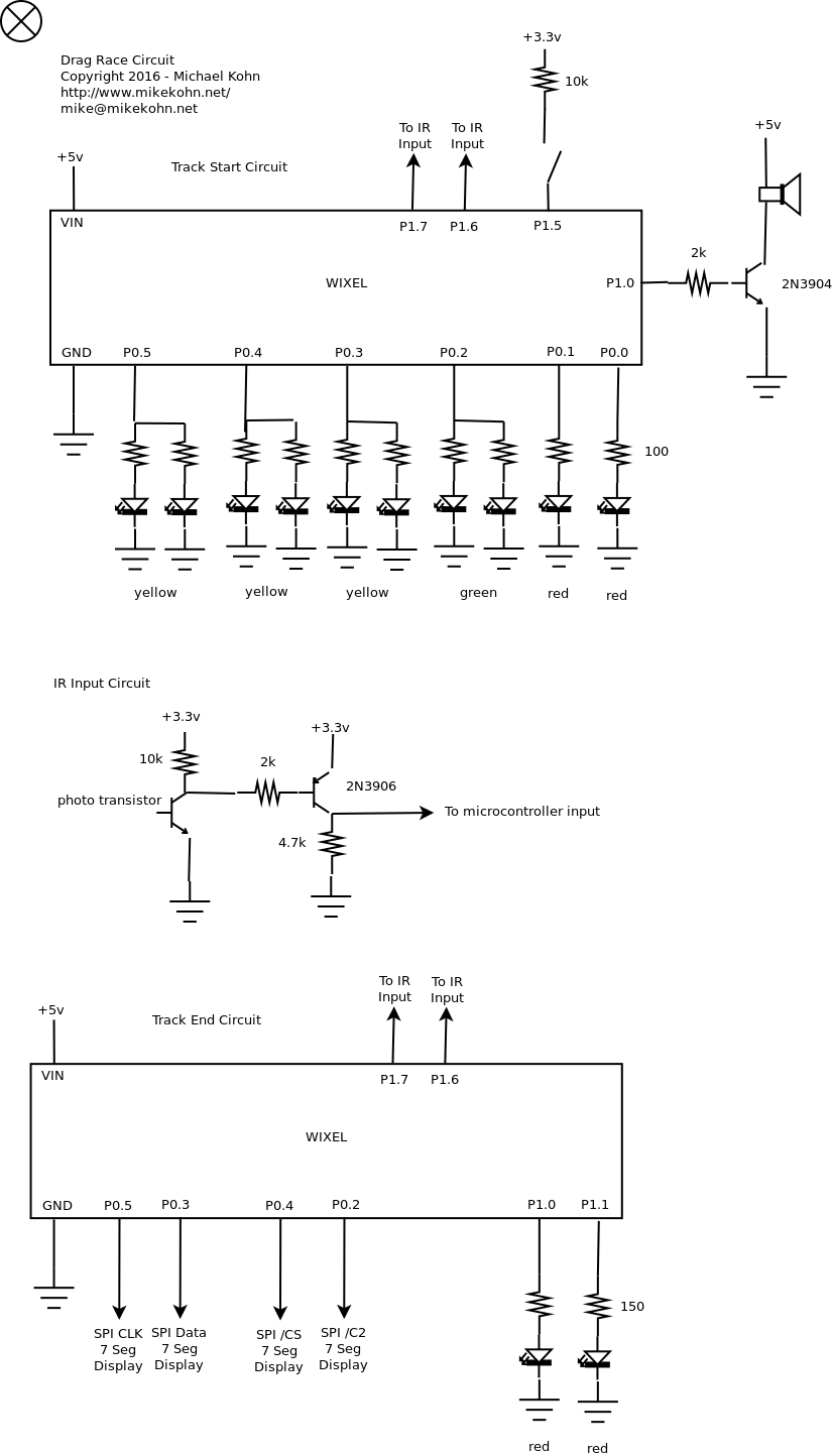
Above is the schematic for the Wixel based circuits.
Version 1: AVR8
The original circuit was done with an Atmel ATtiny2313 for the starting circuit and an ATtiny13 at the end of the track. The sensors to tell if a car starts too early and who crossed the finish line first was done with an infrared emitter and detector that reflected the IR off the car into the detector. The code (available below) is written in Amtel AVR8 assembly and can be assembled with naken_asm.
Here is a video of the original Atmel racing lights being tested. Unfortunately those cars are cheap and hard to control. The surface of the table is too slippery and the cars only have forward, back, left, right as a digital full on or off. YouTube: https://youtu.be/xlghOGqn3ds
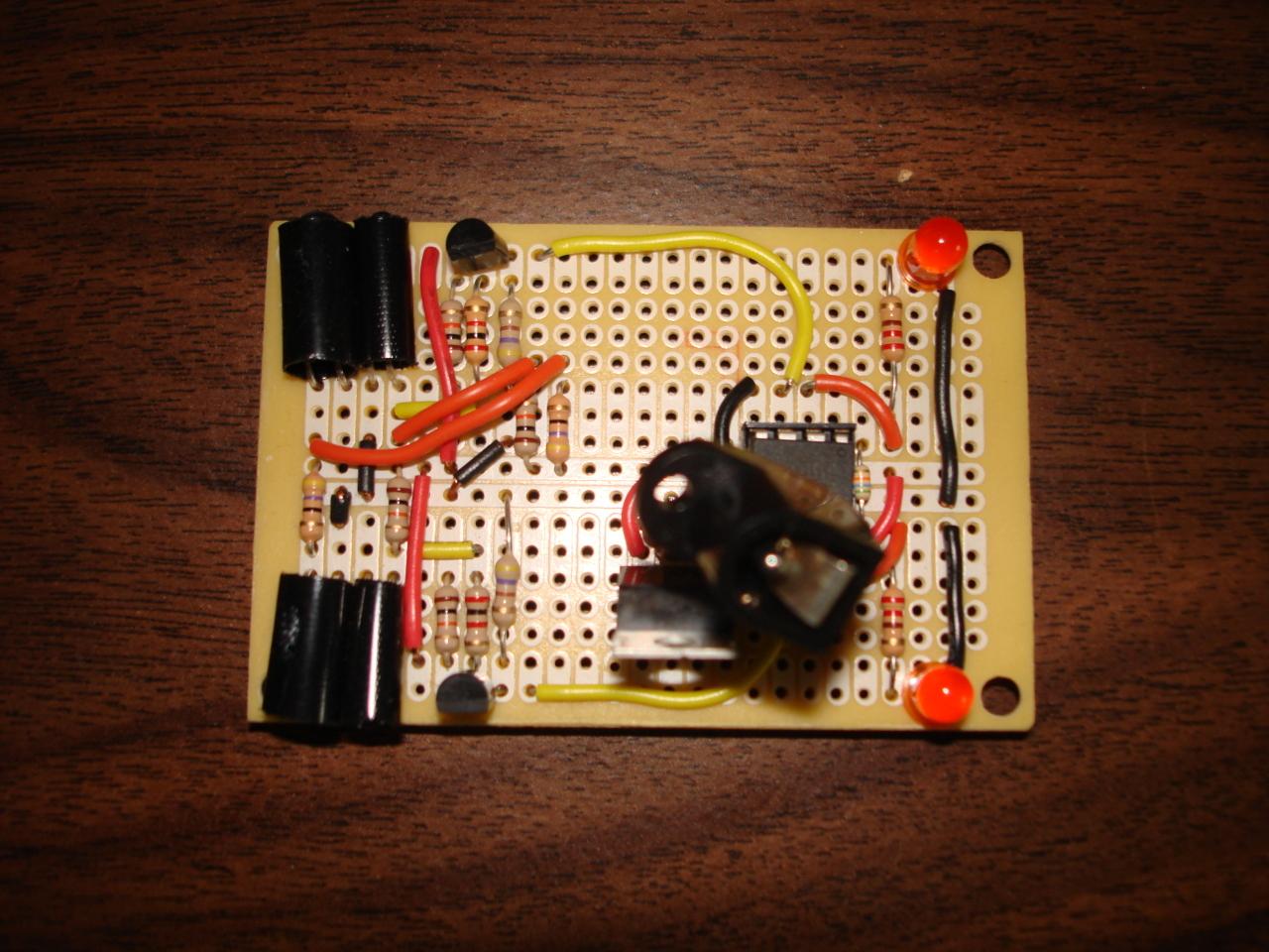
This is the original Atmel AVR8 end of track circuit that's placed at the end of the race track to detect who has won the race.
This is a close up of the original Atmel AVR8 starter circuit. I covered the infrared detector and receiver on both sides with black shrink tubing (unshrunk) just to make sure ambient light doesn't affect the sensor. A couple months after I made this circuit, I recyled the IR emitter / detector for a propeller tachomter that I used to caculate the thrust of some spinning propellers for a couple other circuits.
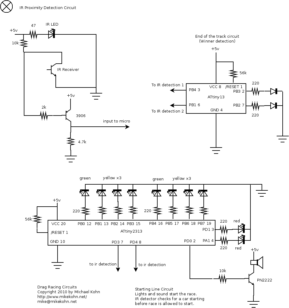
Above is the schematic for the original Atmel based circuits.
Copyright 1997-2026 - Michael Kohn
