Syma S107 No Fly Zone
Posted: January 8, 2012
Updated: January 26, 2012
Introduction
When a friend at work got a Syma S107 IR helicopter to fly around the office, I decided to see if I could jam the signal and create a no fly zone around around my area. A quick search of the Internet and I found several people who already reverse-engineered the protocol. I ended up getting my own helicopter so I could debug this thing. Actually, these helicopters are quite fun, although we both broke a tooth on one of the gears in each of our 'copters so they don't fly as well anymore. At least it flies better than the Linksys Quadcopter project.
Related Projects @mikekohn.net
| Infrared: | Remote Control, IR Guitar Pickup, Sony SIRC Infrared,, R/C Propeller RPM, IR No Fly Zone, Syma Joystick, Paper ROM, Chromebook Remote, Remote Control Food, Alexa TV Remote |
Explanation
The project started with a smaller circuit and different firmware that simply sends a command to the 'copter over and over to prove it can at least be controlled. The IR LED of choice here ended up being a Vishay TSFF5210. The angle of half intensity of this LED is 10 degrees which seems a bit focused, but the radiant intensity is maybe more important. The LED is rated at 100mA continuous and since IR communication is pulsing the LED I decided to drive it around 200mA with a high-gain ZTX1049A transitor. To control the LED an MSP430F2012 is being used since I had some laying around.
The next step was to modify the circuit and source code for jamming. The circuit has 4 IR LEDs in 4 different directions and four Vishay TSOP38223 38kHz IR sensors next to them. When any of the four 38kHz IR sensors senses the remote control trying to send a command, the firmware is programmed to send out its own command on all 4 IR LED's to turn the thrust off. Most likely the 'copter never really sees this command as the IR from the circuit probably just mixes with the remote's IR and creates garbage causing the helicopter to fall from the air.
The firmware is pretty simple. The internal DCO of the MSP430F2012 is set to run at 16MHz (update: 16MHz with the DCO is not recommended). Timer A is setup to interrupt every 210 cycles which comes up to around 76190 times a second (double the 38kHz frequency). Register r13 points to 1 of 2 interrupt routines: led_on, which toggles the output LEDs and led_off which turns all LEDs off. The led_on routine will also count the number of times the interrupt has been hit in the r5 register. This allows the main routine to keep time of how long each "burst" is. For example, when r5 counts to 152, it means 152 interrupts have been called which means approx 2ms has passed.
The IR protocol for this IR controller uses a 38kHz carrier frequency. Transmission of data is done with bursts of the 38kHz flashing IR LED where:
  Header: 2.000ms on / 2.000ms off
       0: 0.300ms on / 0.300ms off
       1: 0.300ms on / 0.600ms off
Transmission starts with a header along with 32 bits of data (and a stop bit) that follow. The 32 bit command is 4 seperate bytes of:
  Byte 0: Yaw      (0 to 127)
  Byte 1: Pitch    (0 to 127)
  Byte 2: Throttle (0 to 127) [ bit 8 is A/B ]
  Byte 3: Trim     (0 to 127)
Yaw, pitch, and trim should be 0 to 127 where 63 is middle. The throttle is is 0 to 127 where the 7th bit (128) will tell it which channel (A or B). Each byte is send LSb first. After each command, there should be a recovery time where the remote stays silent. This project avoids the recovery time in the no_fly_zone.asm firmware so there is the possiblity of sending more commands than the remote sends.
The MSP430 assembly source code below can be assembled with naken_asm assembler.
Video
This video shows the helicopter responding to the movement of the remote control. As soon as the circuit is powered up, the helicopter's signal is jammed and can no longer fly. https://youtu.be/EgWysh5yhGg
Pictures
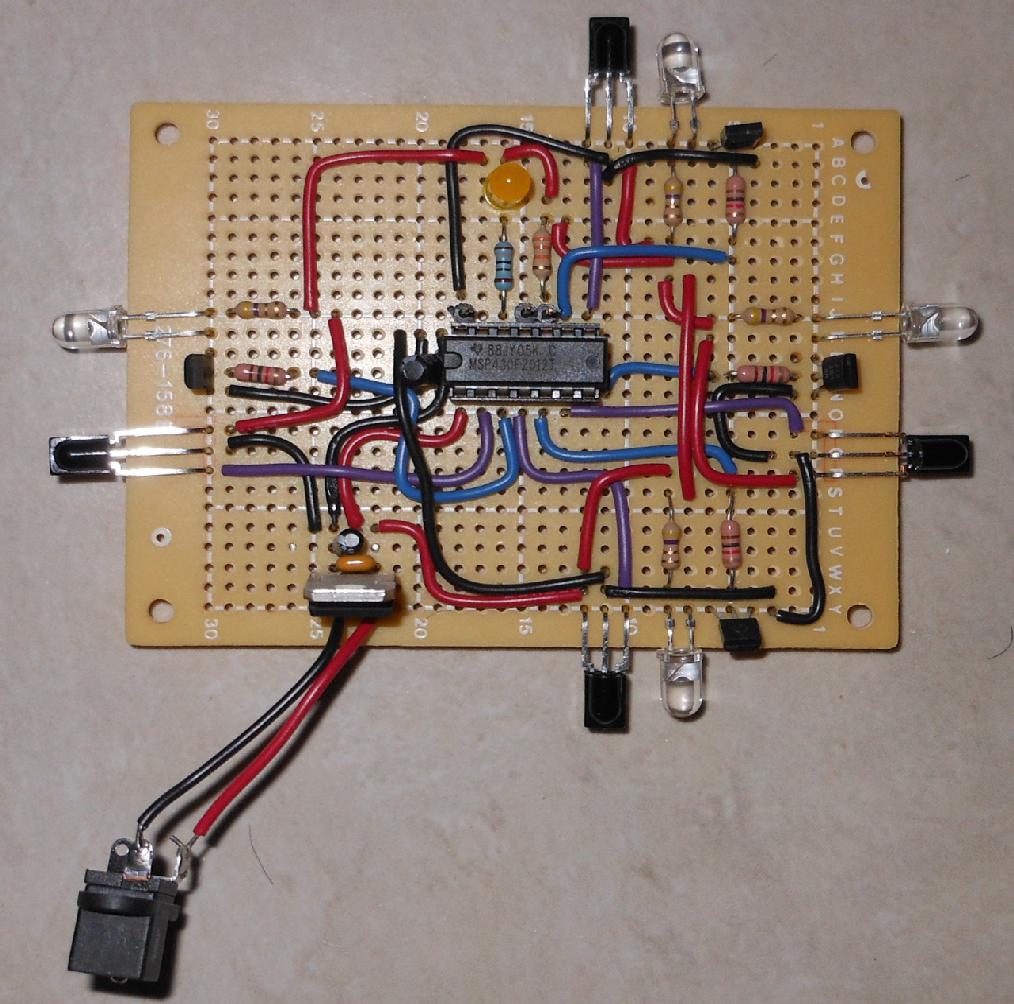
Here's the circuit board. Probably this would have worked just as well with a single IR sensor instead of 4.
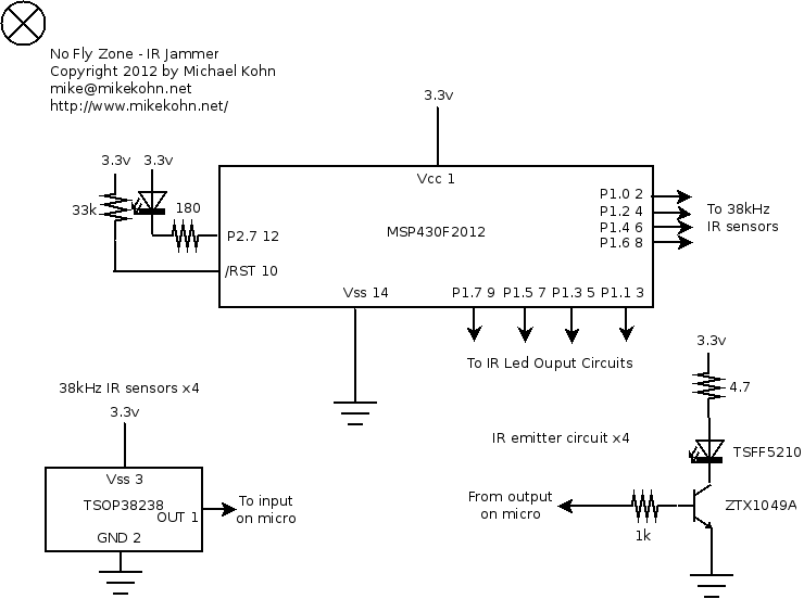
And here's the schematic...
Source code (Updated January 26, 2012)
no_fly_zone.asm
Copyright 1997-2026 - Michael Kohn
