Motion Eyes
Posted: October 27, 2013
Introduction
When I was visiting my parents a couple months ago I found these plastic eyeballs in drawer in the room I was staying in (I guess my parents put these in with the candy to freak out kids during halloween). Anyway, I got this idea of attaching two of these to a couple of servo motors and creating a system to turn the eyes towards motion so I grabbed a couple of them before I went back home. The idea ended up being pretty simple: an embedded Linux device (in this case a Raspberry Pi) with a camera and some software that figures out where the most motion is and sends a signal to an MSP430 circuit to turn servos with the plastic eyeballs towards the motion. The servos with the eyeballs are placed behind a mold of a head that I made by pressing self-drying clay against my own face. My end plan was to possibly put this on a stick infront of my house for Halloween to freak out kids. I probably won't end up doing this though since knowing my luck it would end up getting stolen or destroyed. It will however be decorating my area at work on October 31st.
To assemble / compile the source code below, naken_asm is used to compile the assembly source and fltk-1.3 (sudo apt-get install libfltk1.3-dev) is required to compile the C++ program.
Related Projects @mikekohn.net
| Halloween: | SD Sound, LED Pumpkin Candle, Motion Eyes |
Explanation
The motion detection I'm doing here is pretty simple and took very little
time to implement. The idea I came up with was something like this:
1) Grab image from the camera as YUV and remove the color information (UV).
2) For every pixel in this image, subtract it from the pixel in the previous
image. If the difference in the Y component is greater than a threshold
set the green component in an RGB image to 255, otherwise 0.
3) Count all the green pixels down the RGB image in each column and set the R
pixels of the RGB image at the bottom of the screen based on the G count.
In other words if a column has 100 green pixels, a line
of height 100 is drawn in that column at the bottom.
4) At the column in the RGB image with the highest R count, put a blue mark
at the top of the screen in that column. The blue mark represents where the
biggest motion is.
5) Based on the location of the blue mark at the top of the screen send a
number between 0 and 20 to the MSP430 telling it what position to move the
servos to (0 could be all the way to the left, 10 in the middle, 20 all the
way to the right, etc).
The first video on this page shows how the eyes react using this algorithm. The eyes seemed a little too erratic to me so I changed the code so that if the eyes move to the right, they can't move to the left until a couple seconds have passed and the same with the other direction. If the eyes arnen't detecting motion for a certain amount of time they will center themselves.
The code was originally written using a little Atom based netbook with a built in camera. After it worked the way I wanted it to I compiled it on my Raspberry Pi and got the little camera module for it. Unfortunately I didn't realize the Raspberry Pi camera module isn't supported by video4linux2 so I would have had to rewrite the capture module if I wanted to used it. Being this is the Sunday before Halloween and I have other things to get done, I don't really have the time to do this. Instead I'm using a Playstation 3 USB camera with the Raspberry Pi.
Video
Here's my first test of the eyes with the original version of the software. The computer screen shows how the eyes are "thinking" with the green being the difference between this image and the last, the red at the bottom showing where the most green is, and the blue mark at the top showing where the eyes will move to. https://youtu.be/klBdIY6MXyU
Here it is with the clay face and revised software now running on a Raspberry Pi (oops, forgot to point the camera on the Raspberry Pi.. trust me, it's there). Anyway, the eyes are less erratic since I made changes to the software to make the eyes so they can't change directions unless 2 seconds have passed since the last direction change. Also if there is no motion for a bit of time it will center itself. https://youtu.be/Hk4WaZzpfqc.
Pictures
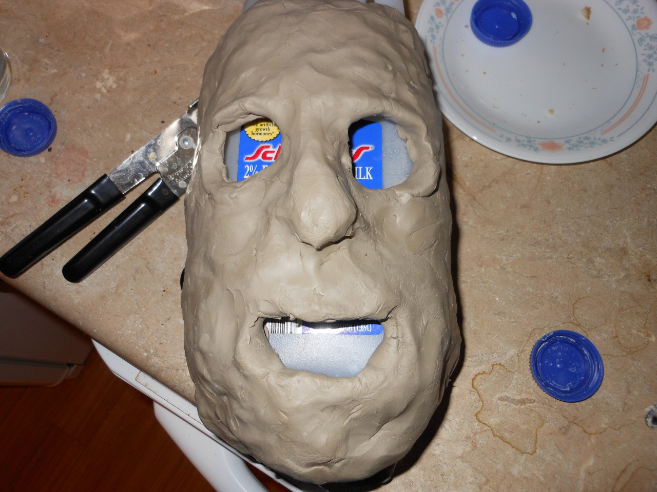
Here's the clay face I'm using. I made this by pressing self drying clay against my face.
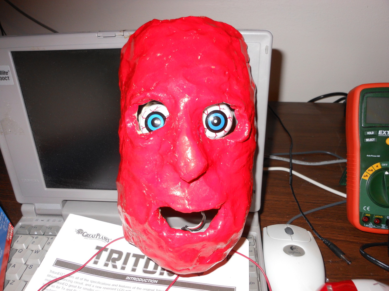
Here's the clay face all dried. I put a coat of polyurethane on it which made it too shiny, so I found a bottle of red paint around the house and decided to paint the front part red. The eyeballs are mounted on the servos which are attached with masking tape to a piece of wood I glued at the top of the head.

Here's a picture from the back of the head showing the servo motors and PS3 USB camera all held in place by masking tape. I would have used something more permanent and stable but I'll eventually take everything back out and use them for other projects.
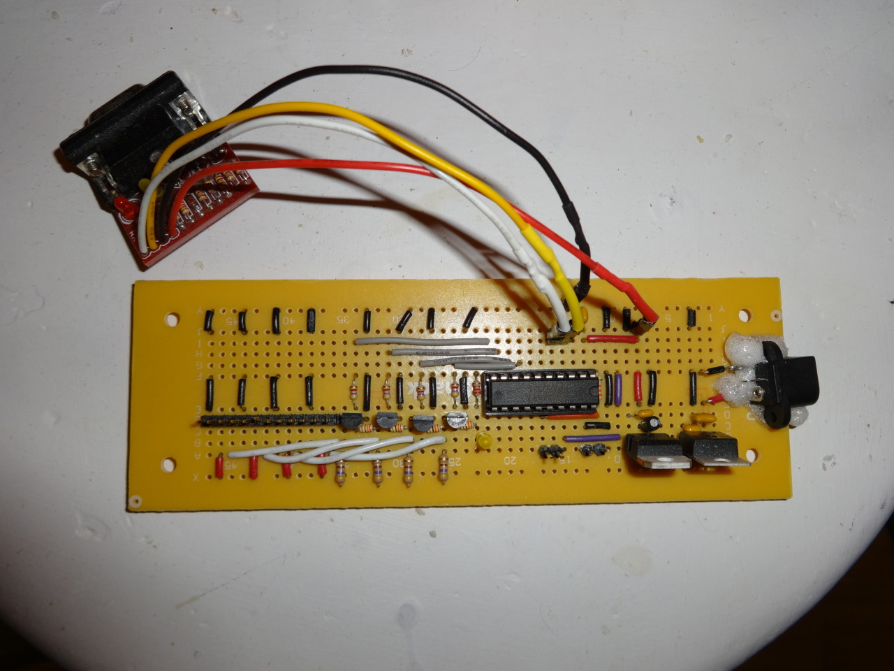
This is the circuit I used to drive the servo motors. I actually designed this board to control the speed controllers on my Linksys Copter v3 (which I need to finish finally).
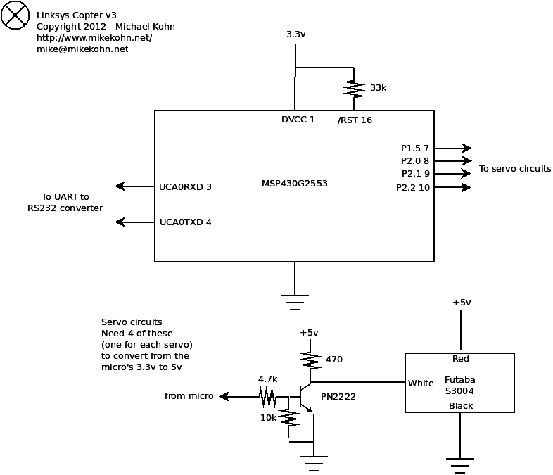
And here's the schematic...
Source code
linksys_copter_v3.asm
motion_detection-2013-10-27.tar.gz
Copyright 1997-2026 - Michael Kohn
