Atmel ATmega168 MOS 6581 SID Player
Posted: March 16, 2008
Introduction
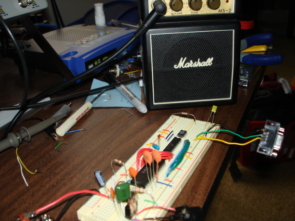
A long time ago I popped out all the custom chips out of a blown Commodore 64. Actually, I think the only thing that had really blown up in the system was the CIA chips, so I figured maybe one day the sound and video chips might be fun to play with. Years and years later (March 8, 2008 to be exact) I finally took the sound chip (also known as MOS6581 or SID - Sound Interface Device) and pushed the thing in a bread board. I added an OPA2134 opamp for the sound output, an Atmel ATmega168 for the CPU, and a DS275 chip to change TTL UART voltages to standard RS232 so I can hook this all up to a Linux box. The sound output of the entire system is run into a Mini-Marshall guitar amp.
My ultimate goal here was to write software for Linux that can in real time send .mid songs through the Atmel chip into the SID to play music. One thing I have to say after finishing this project, I find it interesting how in 1983 you can buy a book that has everything about a computer, including chip pinouts and schematics, but today everyone tries to keep how their hardware works as secret as possible. Sad.
Related Projects @mikekohn.net
Pictures (Click To Enlarge)
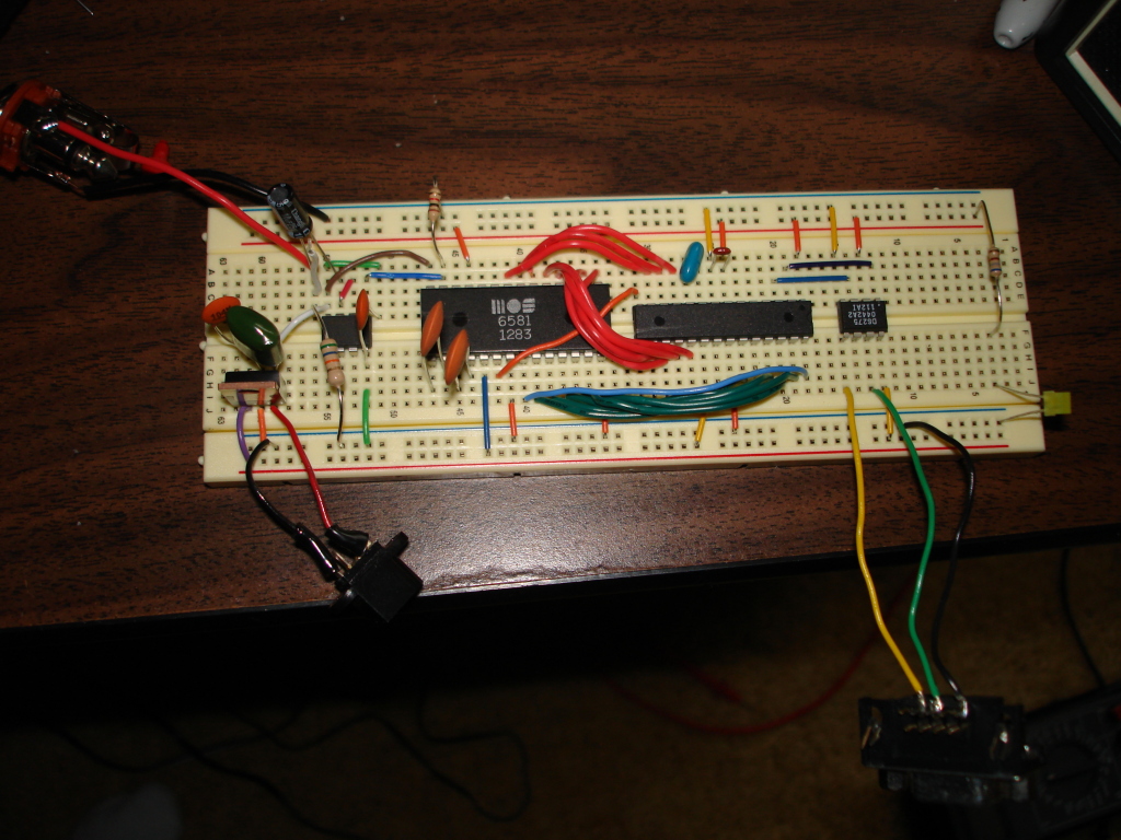
Explanation
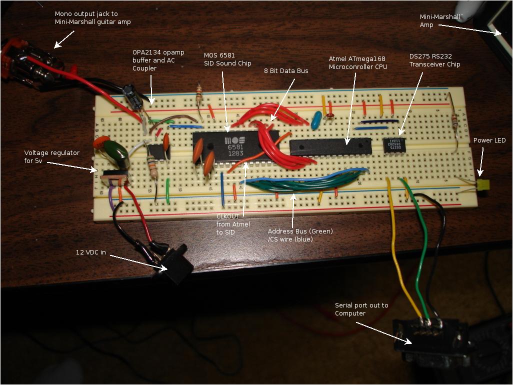
So this circuit (as you can see from the labeled picture above) has basically 5 distinct pieces. The first piece to the circuit was getting 12v and 5v supplies. I accomplished this with the simple 5v voltage regulator circuit. Since the output of the SID is 6v max, I used the 12v supply on an OPA2134 opamp giving me a 6v cushion to the rails. The opamp is a simple buffer and AC coupler circuit which removes the DC offset from the SID chip.
The next piece to the circuit is the SID itself. It runs both 12v and 5v. One thing to note is I couldn't find the 2200pF capacitors that the book recommended at Radio Shack so I ended up using 4700pf. I believe they are just used as filters and the only real requirement is they are identical. The book recommends a bypass capacitor both on Vcc and Vdd, but I elected not to put them to save space on the board. One important fact I found out the hard way: the 1k ohm resistor from the audio-out pin to ground needs to be there, otherwise it outputs some kind of garbage that almost works.
The next piece is the Atmel ATmega168 microcontroller. The SID is connected to the ATmega168 through an address and data bus. The address bus is the green wires and they are connected from the SID's A0-A4 pins to PORTC on the Atmel. There is a blue wire there too that gets connected to the last bit on PORTC. This is the chip-select signal that is "strobed" from the Atmel chip to let the SID know there is a new value sitting on the databus to read in. The red wires from the Atmel to the SID are the databus. Unfortunately I did not have enough free pins on PORTB so I had to split it up between PORTB and PORTD. Yeah, it makes programming the thing a little more difficult, but I wired it in a way that would reduce the number of instructions needed (aka, no shifts needed on PORTD). CLKOUT from the Atmel chip is wired to the theta (clock in) pin on the SID. The Atmel here is running with a 4MHz resonator and is clock divided by 4. Btw, to make sure the SID never gets more than 1MHz, I set the CLKDIV8 fuse when programming the chip so clock out starts out at 0.5MHz.
The last piece is the DS275 chip. This is used to turn the TTL serial port voltages into RS232 voltages as shown in my Atmel RS232 project.
Schematic

The Software
On the Atmel chip itself, I wrote some firmware that basically listens on the serial port for certain commands. A command of 0xfe means it should output 3 lines with the firmware version and copyright. A command of 0xff means two more bytes will follow. The second byte will be the address to "poke" to and the third byte will be the data to poke into that address.
On the Linux side, midi_sid_play.c simply parses a .mid file translating midi events into my protocol and sending commands over the serial port.
I was actually tempted to just make the Atmel chip understand MIDI, but it seemed kind of worthless to me unless I fully implemented the hardware which I didn't really feel like doing. Plus I think I can't get my baud rate high enough running the chip at 1MHz. For a later project I might make a kernel module to create a /dev/midi device for the thing.. not because it would be useful, but just so I can learn how to make kernel drivers.
Sound Sample
The sid_player.mp3 file is the inv2v13a.mid file played through the midi_sid_play program into the circuit. I recorded this through a Shure SM-57 microphone into an M-Audio FastTrack Pro into Garage Band on a MacMini :).
Of course for this project I had to use the Commodore 64 theme song :).
Download
sid_player-2008-03-16.tar.gz
sid_player-2008-03-16.zip
NOTE: This code is written for the ATmega168. This processor memory maps the UART registers into SRAM. Other Atmel chips might need in/out instructions instead. Using this as a guide it should be pretty simple.
Copyright 1997-2026 - Michael Kohn
