MSP430 Cluster
Posted: February 20, 2022
Introduction
After finishing up the Mandelbrot cluster project with Kubernetes, I kind of wanted to try building a cluster of microcontrollers to compute Mandelbrots. This project is a set of MSP430G2231's sharing Vcc, GND, and SPI lines to a single Rasperry Pi 3 with code written in Python to control them.
Before starting, the RPI uploads a Mandelbrot routine (written mostly in Java) to all the MSP430's. After that, another Python script finds an idle MSP430 and runs it for (x,y) locations later downloading the return value back to the RPI. Based on the value, a color is inserted into the image.

Above is the final image after being run on the cluster. Even though it was a 640x480 image, the image is a bit pixelated due to the low resolution of he fixed point registers.
The source code is included with the parallel computing Mandelbrots project and below is a bigger explanation of this project.
Related Projects @mikekohn.net
| Mandelbrots: | Mandelbrots SIMD, Mandelbrot Cluster, Mandelbrot MSP430 |
Explanation
The project starts with a series of 4 small PC boards with an MSP430G2231 soldered onto it. On each side of the MSP430 are a set of 8 pin female headers. The pins on the header are pretty long so the boards can be connected and pulled apart if needed. on the top boards, all pins were cut except +3.3v, GND, and the 3 SPI pins. This way powering the bottom board and connecting its SPI pins to the Raspberry Pi connects all the microcontrollers to power and SPI.
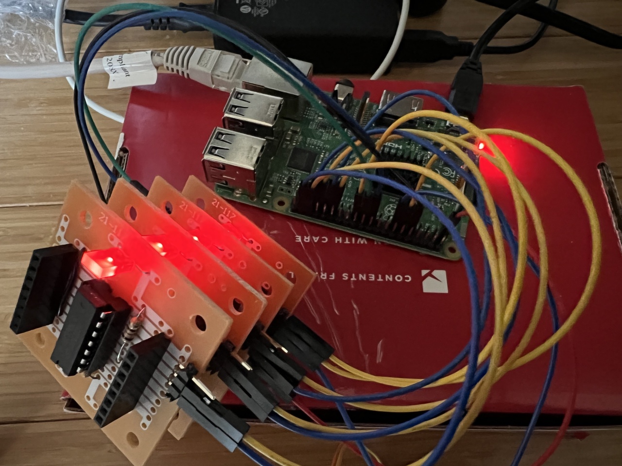
The image above shows the 4 boards connected to the Raspberry Pi. Each MSP430 has 2 unique signals: a yellow wire for chip select and a blue wire to signal to the Raspberry Pi that the node is currently busy or not listening to SPI.
The main firmware on the MSP430 is a simple program that listens to SPI for a command. The commands are numbers 1 to 4:
1: download program
2: run program
3: set param 1
4: set param 2
So for this system, there is a Python script called cluster_upload.py. This program will send a binary program to a single MSP430 node that will get stored in location 0xfa00 of the MSP430's flash. When the cluster_run.py program runs, for each pixel it will find a free node and set param 1 to the current real mandelbrot value and param 2 to the current imaginary Mandelbrot value. After that the command is sent to run the routine and later when the busy signal of chip goes low, the Python script will download the return value.
The Mandelbrot code itself is written in Java and compiled with Java Grinder. Although Java Grinder does have support for a software multiply, since the registers are 16 bit it loses the top 16 bits of the result, so there is a little bit of inline assembly for a 16 bit * 16 bit to 32 bit multiply routine in the Java code. The values are all fixed point where the upper 4 bits are the whole number and the bottom 12 bits are decimal part.
SPI
This is the first time I've used a microcontroller's SPI in slave mode, in this case the Raspberry Pi is the master for all 4 nodes. The MSP430G2231 uses what TI calls the USI module for SPI and i2c. The bigger MSP430's seem to typically have a USCI module which seems a little more advanced, but I've always seem to have more trouble using them. Unfortunately, the USI module doesn't have a hardware chip select. Which means any time something is transmitted over SPI, all the chips would read the value. Some kind of unfun code was wrapped around the SPI code to deal with it. Unfortunately, I was having a really hard time with the hardware SPI, so after struggling for a while I decided to just do a software SPI. Ended up getting that working pretty quickly. Unfortunately, that also means that the SPI clock on the RPI is pretty slow.
Writing To Flash
This was the first time I've updating flash memory on a microcontroller while the program was running. If I understood correctly, the MSP430 separates the flash program memory by 64 byte segments, so the memory location 0xfa00, far enough away from the main firmware, was chosen as an address to store the Mandelbrot code. There are two things that have to be done to write to the program memory. The first thing is do an erase cycle on all the memory that will be overwritten. This changes all the values in flash to 0xff. The second is to write each byte to program memory. The write cycles have to be between 514kHz to 952kHz, so since the DCO is running around 12MHz a divisor in FCTL2 is used to bring it down to that range. Actually, looking at that code now, it seems I made a mistake and used a divisor of 32 instead of 17 or so. Before I set this divisor, I was using a divisor of 1, which kind of worked, but would get some errors every X number of bytes or so. There is a checksum computed internally, but requires a debugger to view it.
Performance
The results are actually a little sad:
4 Cores:

0: 76800
1: 76800
2: 76800
3: 76800

real    21m11.261s

-----------------------------

3 Cores:

0: 102400
1: 102400
2: 102400

real    21m26.557s

-----------------------------

2 Cores:

0: 153798
1: 153402

real    28m48.481s

-----------------------------

1 Core:

0: 307200

real    50m11.725s
The first set of numbers shows how many pixels were calculated on each core while "real" is the amount of time it took to compute the image. With 3 and 4 cores, the number of Pixels between each core was evenly dispersed , which gives me the impression that it takes more time to check each chip to see if it has a finished value and run a new value than it does to compute a pixel.
Source code
git clone https://github.com/mikeakohn/mandelbrot_sse.git
Copyright 1997-2026 - Michael Kohn
