Water Optic Communication
Posted: Septmeber 28, 2020
Introduction
I was recently watching the TV show Modern Marvels where they were doing this episode on "glass" and spent some time showing how fiber optic cables work. They showed that the concept of total internal reflection also applies to water (I believe they had the bucket of water with a hole so water was flowing out of it in a curved shape with a laser beam bouncing through the stream.. if not I saw it somewhere else). I was curious if I could fill a rubber hose with water and transmit data through it using a bright LED using this property.
I ended up getting it working and it's like... speed of light fast! Well, speed of light blinking UART at 9600 baud. I used a Microchip ATtiny85 that basically relays the signals from a USB/UART cable. When the micro detects the UART TX as signal high, another pin on the micro is set high which drives a 65,000 mcd LED through a transistor. On the other side of the system is a 850 nm photo diode connected to an opamp. The ATtiny85's ADC queries the voltage on the output and if the voltage is above a threshold it will set the pin connecting to RX high.
Video, pictures, source code, and explanation below..
Related Projects @mikekohn.net
| Storage: | Tin Can Modem, Water Optic, IP Over Lasers |
Video
Here's a video of the system showing it working with a high-level explanation. There's also a demonstration of a rubber hose without water in it showing that no data is transmitted without the water. https://youtu.be/Mk4rtyzDQp8
Pictures
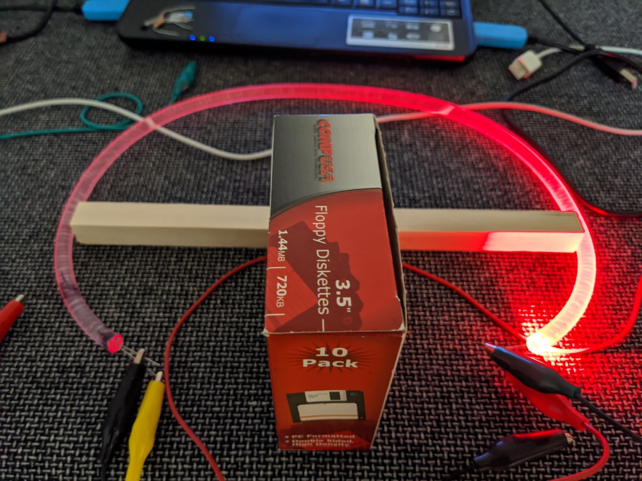
Here's a picture of the tube of water that carries data. Since the TX signal of the transmitting UART is on, the LED stays on until it gets a start bit. I put a box of floppy disks to block any light from the LED going directly to the photo-diode. I believe it's not even close to bright enough to be picked up, but just in case it's there. The rubber tube is curved showing the light does reflect through the tube.
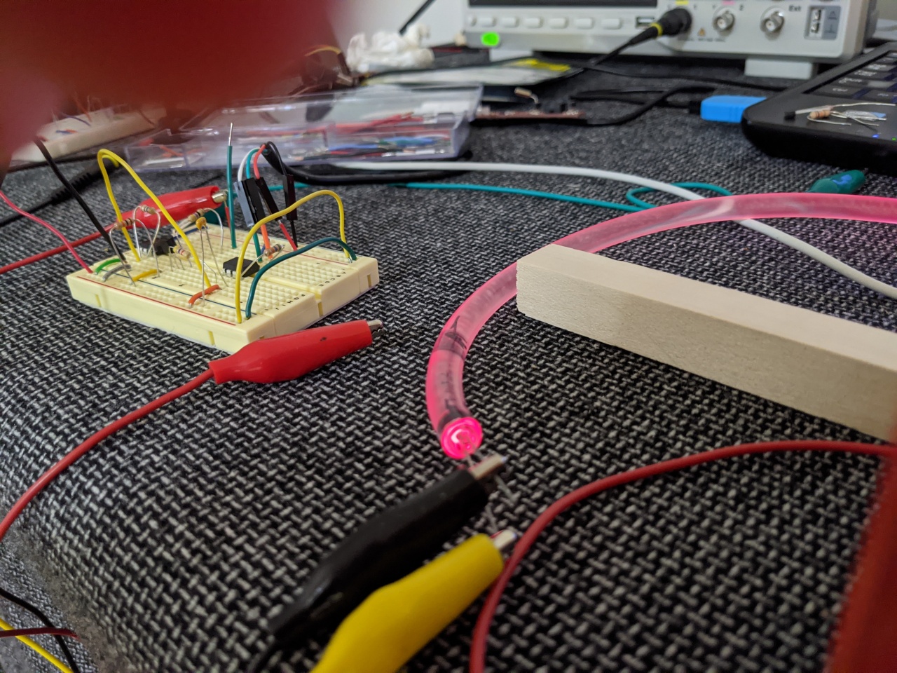
This picture shows the photo diode end of the system. Since the light is on and reflects through the water, the photodiode has a red glow to it. The system probably would have worked better with an opaque tubing, but being able see the light makes it look neater.
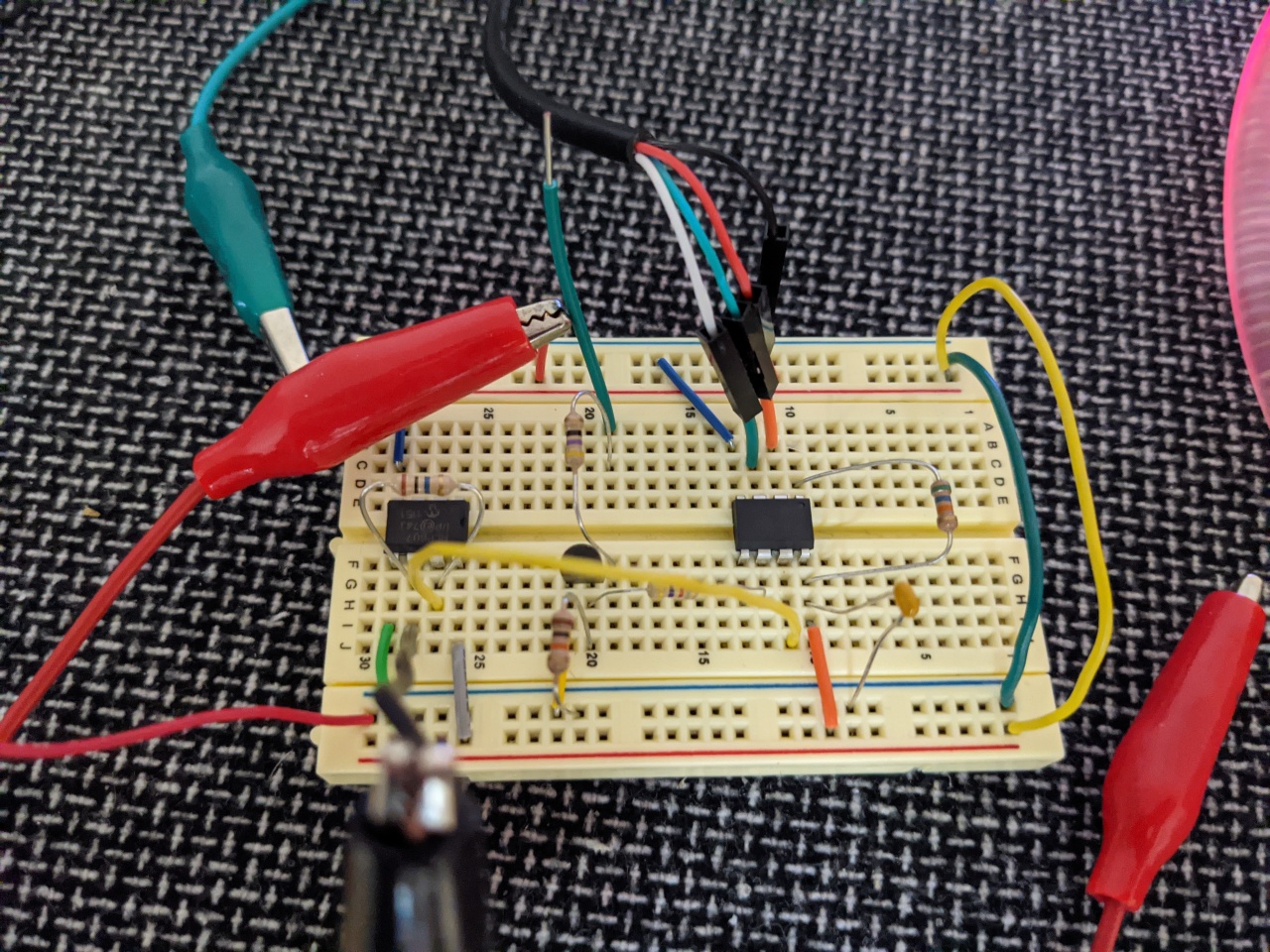
This is the circuit board that drives system. Originally I was going to do two way communication so everything is there to drive an LED from this side also through a second tube.

This is the circuit board that drives system. Originally I was going to do two way communication so everything is there to drive an LED from this side also through a second tube.
Explanation
Most of this system was really not that difficult, and I was originally planning two way communcation and possibly tunnelling an SSH connection through the water. Unfortunately I had a really hard to time with the light detection part so I decided not to go that far.
I started out by going to the hardware store and buying a rubber hose with a ~5mm inner section. This way a simple 5mm LED and 5mm light detector would fit snug and plug the water from leaking. I got the brightest LED I could find, which ended up being 60,000 mcd and red. I debated if I should try blue instead, but since from what I've read blue travels better, but I stuck with red. Red is more easily seen too in the water I think. I did consider a laser, and actually kind of tested one that I used on the drag race project, but I'm not sure it did much better than the LED and it wouldn't have plugged the rubber hose. I'm not sure if this helped or not but I used distilled water hoping that less impurities would help transmit the light better.
For the light detection circuit, I tried using a photo-transistor and the same detection circuit I used in a Drag Racing Tree (which used a laser) and a tachometer circuit which used an IR transmitter. Unfortunately the difference in voltage for this light was only around 0.2 volts, which there was also some noise around there. I ended up using a photo-diode with an opamp instead. With the photo-diode / opamp I was seeing almost 0v when the LED was off and something like 1 to 2v when the LED was on. There was some noise, but with the ADC and just watching for a certain voltage threshold it worked flawless.
For the firmware, I was originally thinking of doing a protocol similar to the tin can modem project.. so it would read a byte with a software UART, transmit it with multiple length flashes as a data format, etc... but then I realized I could just flat out turn the TX voltage signal to light and translate the light back into voltages with the analog to digital converter. So really the firmware is just a relay. I used 9600 baud for a UART transmission rate, probably could have went a lot higher, but just 9600 is cool.
A side note, at some point I considered not using a microcontroller at all, but when I was using the photo-transistor the voltages I was getting were between something like 4.3 to 4.4v or something depending on if there was light or not. A microcontroller to detect that seemed to make more sense to me. With the photo-diode I probably could have used a transistor to change to 0v or 5v depending on if there was light or not but I already had the microcontroller set up.. plus I'm a software guy.. not really hardware.
Source code
relay.asm
Source code assembles with naken_asm.
Copyright 1997-2026 - Michael Kohn
