IP Over Lasers
September 29, 2025
Introduction
A typical computer is connected to the local network using either an Ethernet cable or WiFi. This project connects two computers together through lasers.
This project takes advantage of the Linux support for a tun (tunnel) network device. Like any other network device, it gets its own IP address. The difference is, when network traffic is routed to it, a user land computer reads in the data and from there can do whatever it wants with it. Likewise, packets can be written to the tunnel device and the kernel will use it the same as if it came from a hardware network card.
Explanation, video, pictures, and source code below.
Related Projects @mikekohn.net
| Storage: | Tin Can Modem, Water Optic, IP Over Lasers |
Video
YouTube: https://youtu.be/U-pM_YwO_94
Above is a video with a demo and short explanation of the project. One mistake I make while making the video, I was playing around with different baud rates while having some problems and thought I left it at 2400 baud. It's actually running here at 1200 baud, but it does for sure work at 2400 baud.
Explanation
Both computers (in this case a laptop and a Raspberry Pi 5) have USB-UART cables connected to them. Those cables are connected to two pins on ATtiny85s. The ATtiny85s on two other pins have a laser and a phototransitors. Each laser is pointed to the phototransistor on the opposite microcontroller.
Originally, the plan was to try to use a 38kHz IR sensor, so the lasers would flicker at 38kHz when they were on and light "noise" would therefore not affect the system. It actually seemed to detect the laser sometimes, but it was kind of obvious it wasn't going to work so instead a phototransistor is used.
I did use these lasers for other projects, including the Drag Racing Tree circuit and never used eye protection. Kind of realized that was probably a really stupid idea so I ordered some cheap $10 goggles. It made working on the project more difficult, but better to be safe than blind.
Using minicom, data could be transferred character by character over the lasers at 4800 baud. At 9600 baud only garbage was transfered. I was having trouble with the relay of IP data so I dropped it down to 2400 baud. There were some bugs in the code at that time so maybe it could be bumped back up to 4800. Either way, ping time isn't pretty and connecting using SSH takes... a minute or so.
ATtiny85
The code running on the ATtiny85 is extremely simple. The pins are set up like this:
  ;; PB0: UART-TX (output)
  ;; PB1: UART-RX (input)
  ;; PB3: laser-out
  ;; PB4: light-in (reverse logic)
From the UART cable, the TX pin is connected to the PB1 in and the RX pin is connected to the PB0 pin. Code does the following logic:
Input:
  If PB1 is set as 1, PB3 is high (laser on).
  If PB1 is set as 0, PB3 is low  (laser off).

Output:
  If PB4 is 0 (the laser is on)  PB0 is high.
  If PB4 is 1 (the laser is off) PB1 is low.
laser0 / tun0
The tun0 device is set up with the follow commands:
Computer 1:
  sudo ip tuntap add mode tun dev laser0
  sudo ip addr add 192.168.3.101/24 dev laser0
  sudo ip link set dev laser0 up

Computer 2:
  sudo ip tuntap add mode tun dev laser0
  sudo ip addr add 192.168.3.100/24 dev laser0
  sudo ip link set dev laser0 up
Each computer runs a program called relay. This program simply sits in a while loop that does simply this:
  * Check tun0 for a packet. If packet is available read into buffer and
    send out UART.

  * Check UART for data. If data is available read in 4 bytes to see if
    it's 0xff 0xff and the next 2 bytes are number of bytes to read for
    the size of the packet. Read in the read of the packet and then transfer
    to tun0.
Pictures
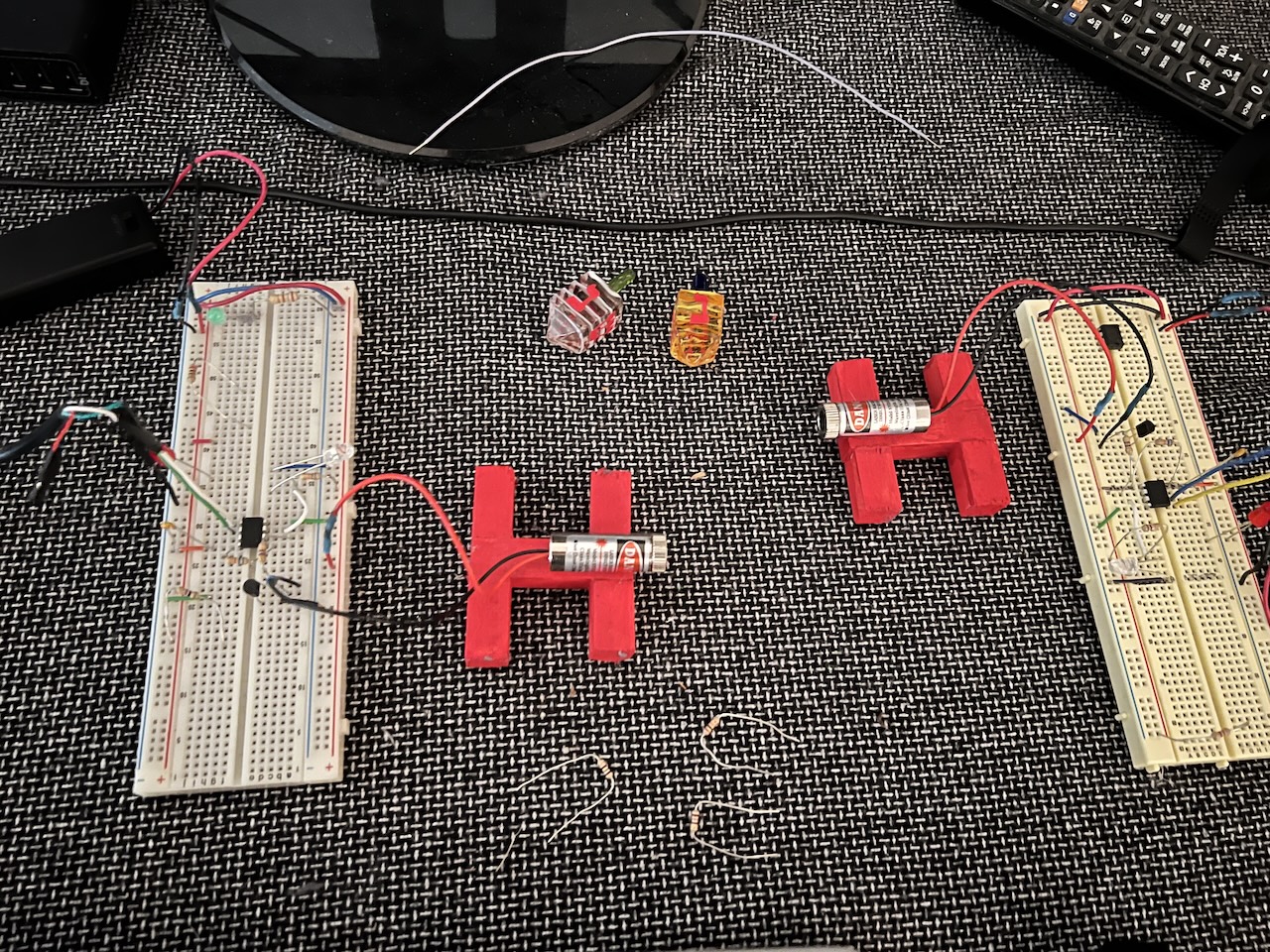
Above is a close up picture of the two circuits and the two lasers. Each circuit runs on 3v of battery which was nice since the battery holders had on/off switches. This allowed me to turn the lasers off if I needed to make some code changes.
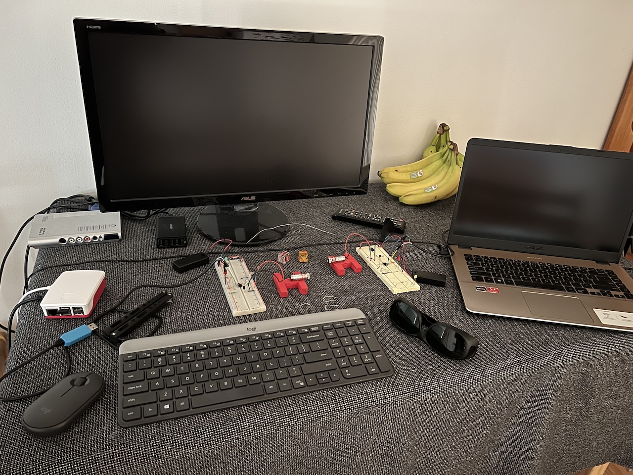
And this is bigger picture. Between the two computers are the laser saftey goggles I used for eye protection.
Source Code
https://github.com/mikeakohn/small_projects/tree/main/ip_over_lasers
Copyright 1997-2026 - Michael Kohn
