Tin Can Phone Modem
Posted: July 3, 2020
Introduction
Here's the popular "science experiment" of a phone made from tin cans and some kite string. This time instead of sending voice from one can to the other, data will be sent using a short beep for 0 and a long beep for 1 with a longer start beep to begin the transmission. A transmitter circuit on one end takes data from UART cable to a PC and relays the data through a speaker in one can. The receiver circuit has a microphone in the can and UART cable to relay the response back to the PC.
This project was quite a bit more difficult than it looks. I'll have to admit my strength is software, not analog circuits. I messed with this a few months back with some other materials but got frustrated and decided "life's too short" and quit. A couple weeks ago I felt like trying one more time and finally got it working. More on that in the explanation below along with a video, pictures, schematic, and source code.
Related Projects @mikekohn.net
| Storage: | Tin Can Modem, Water Optic, IP Over Lasers |
Video
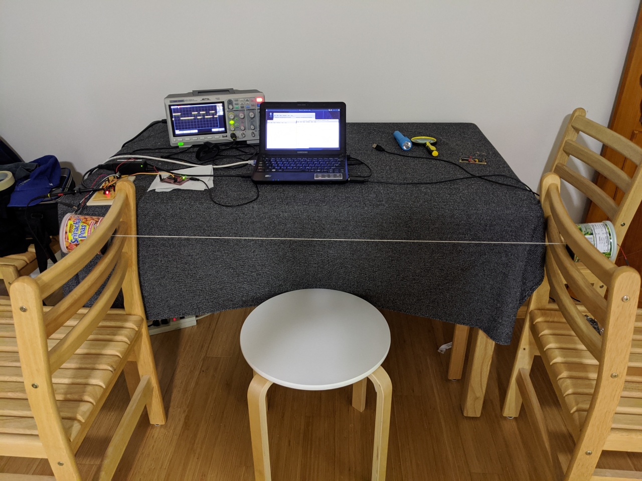
Here's a video of the circuit working. Two tin cans (Sriracha peas receiver and wasabi peas for transmitting) are held up by 2 chairs in my kitchen. I was able to adjust the tension on the string by moving the chairs further apart. The receiver circuit is hooked up to the oscilloscope to show if the data getting passed is bad so the the tension on the string could be adjusted to get a better transmission. The data transmitted is simply my name. At the end the string is loosened to prove no data is picked up if the string isn't vibrating.
I rarely talk in videos, but I decided it makes more sense to try to explain things in this one. I realized when I finished I forgot the mandatory 2 minute introduction and begging people to click the like button and to subscribe.
Explanation
This project is conceptually quite simple, pretty simple software-wise, but really a lot more difficult than it looked due to so many electrical and physical variables:
- Use of tin cans or paper cups.
- Type of string used (kite string, fishing line, dental floss).
- How much tension on the string.
- Type of microphone.
- Carrier frequency (400Hz, 800Hz, 1000+ Hz).
- Type of preamp (MC607, OPA2313, LM386).
- Gain of the preamp.
- Capacitors used on LM567 (changes sensitivity, bandwidth, etc).
- Length of tones and spaces.
When I originally tried this project, I started out with tin cans and kite string. I was having trouble so I next tried fishing line but later read that using a string that can't strech would work better. The website also recommended paper cups so I got a couple lattes from Starbucks and tried some dental floss.
The two original circuits were both based on ATtiny2313 microcontrollers. I used these Atmel chips because they can run at 5v instead of the 3.3v the MSP430 runs at. Since the LM567 chip I used to detect the tone I was transmitting runs at 5v, I figured it would make the circuitry simpler to use 5v microcontrollers. The whole system is quite similar to a Tape Data Recorder project I did earlier, except this time instead of recording the data to tape, it will play the data through the cans.
The transmitter side is really simple. The ATtiny2313 reads in data through the UART and toggles a data pin at a frequency to send out sound through an LM386 audio amplifier into the speaker. The length of the tone tells what kind of data bit it is: very long is a start bit, half that is a 1, and a little shorter than that is a 0. The loudness of the tone can be adjusted with a potentiometer to make sure the sound can't be picked up by the microphone if it's not through the string.
On the receiver side an LM567 serves as kind of a bandpass filter and has an output signal that will show no voltage if the configured frequency is detected on the input. To configure it, a capacitor and resistor combination is connected to pins 5 and 6 to select the frequency desired. On pins 1 and 2 capacitor values there will select how sensitive the chip is (how quick it will detect the signal and how quick to release if the frequency starts to disappear) and the bandwidth (how far off from the selected frequency should be okay to report that the frequency exists).
I originally tuned the LM567 to detect a tone around 800Hz. I can't remember the exact frequency, but it was based on some simpler resistor / capacitor setup. I got the whole circuit working and detecting the tone before setting everything up in my kitchen using Starbucks cups and dental floss. The dental floss was tied to the inside of the cups using broken toothpicks. The biggest problems I had with that setup were the dental floss tended to break a lot when pulling the cups tight. I also had a really hard time finding the correct opamp gain and capacitors for frequency detection. The signal (before it reached the LM567) was pretty noisy.
So like I mentioned above, after I spent some time on this on some weekends I decided to give up.
A couple weeks ago I decided to try this again. I was going to go for 1000Hz this time and was thinking of trying an MSGEQ7 graphics equalizer chip instead. Decided in the end that wasn't the right thing to do and went back to the LM567. This time I set up the resistor / capacitor on pin 5 and 6 for 1000Hz. I also used a SparkFun Electret Microphone Breakout board which already has the opamp circuit. It wasn't quite loud enough so I used a second stage MCP607 with a gain of 10. Pretty much perfect.
I also went back to the tin cans and kite string and switched the circuit to MSP430. The Amtel chips just don't have the same debugging tools that the MSP430 has. A $10 Launchpad along with mspdebug and naken_asm (both programs together will fit on a 3.5" floppy) and I can ctrl-C to stop the code and examine registers and memory. Unless there are some opensource tools I don't know about, to do Atmel debugging requires a pretty big IDE download along with a Windows system. Hopefully Microchip will fix that. In the receiver firmware I would dump the lengths of all the pulses into nine 16 bit memory locations and examine them to see what went wrong.
I set up the LM567 and played a 1000Hz tone using a website that can create tones and found the LM567 ignored it. So I made sounds using my voice and found a frequency it does react to. Using my guitar I found it to be 400Hz and decide to just go with it. I still have no idea why this is 400Hz. I checked the values of the capacitor and resistor with a multimeter and ran the calculations many times over. It should have been 1000Hz. Anyway, here are the values I came up with that seemed the most stable:
- R1 = 2.7k
- C1 = 0.33uF
- C2 = 0.0047uF
- C3 = 1.0uF
I used a multimeter to get more exact values for R1 and C1 (2.6k and 0.337uF).
Using the equation in the datasheet:
frequency = 1 / (1.1 * R1 * C1)

octave:2> 1 / (1.1 * 2700 * 0.00000033)
ans =  1020.3
octave:3> 1 / (1.1 * 2660 * 0.000000337)
ans =  1014.1
I tried to use the same values in the datasheet for C3 and C2 but C3 needed to be much higher to get the stability needed.
I was originally hoping to get close to 100 baud or so, but after struggling so much I went with a transfer rate between 6 to 7 baud. If I have my math right:
Minimum rate based on 200ms START, 100ms ONE, and 50ms SPACE:
octave:7> (1000 / ((200 + 50) + ((100 + 50) * 8))) * 9
ans =  6.2069

Maxiumum rate based on 200ms START, 75ms ZERO, and 50ms SPACE:
octave:8> (1000 / ((200 + 50) + ((75 + 50) * 8))) * 9
ans =  7.2000
So old old old telephone modems used to use 4 tones, two for the caller as 0 and 1 and two for the callee as 0 and 1. For one way communication this would have required two LM567's so I instead used the same encoding typically used on IR remote controls (also the same as Tape Data Recorder and Pancake-ROM). In this case a start bit lasts 200ms, a 1 bit lasts 100ms, a 0 bit lasts 75ms, and a space between the bits is 50ms.
Below is a view of the whole system sitting on my kitchen table. On the left is a sriracha peas can (red/orange wires and can for receive) and on the right is a wasabi peas can (green wires and can for transmit). This time around I used kite string and metal cans. The cans are attached inside the can through paperclips. Not sure how their position in the can affected the transmission quality, they probably moved a bit when I tightened or loosened the string. If I put in my hand on the string while the tones were playing, I could feel the sound on the string. It was a pretty strong vibration.
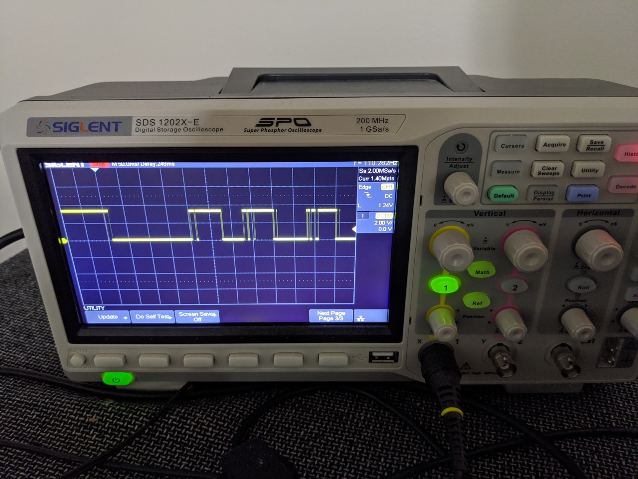
Below is a view of the oscilloscope with the probe just after the LM567 showing the input signal going into the MSP430. This was actually a pretty clean run, most of them started with spikey noise infront of every tone and sometimes spikes in the middle. To compensate for that I digitally filtered those out in the interrupt routine (every 1.25ms) which would increment the R4 register if the LM567 signal is low (tone detected) up to only 20 counts and decrementing R4 if the signal is high (no tone detected). If R4 is above the lower treshold of 5, then it considered the tone to be playing.
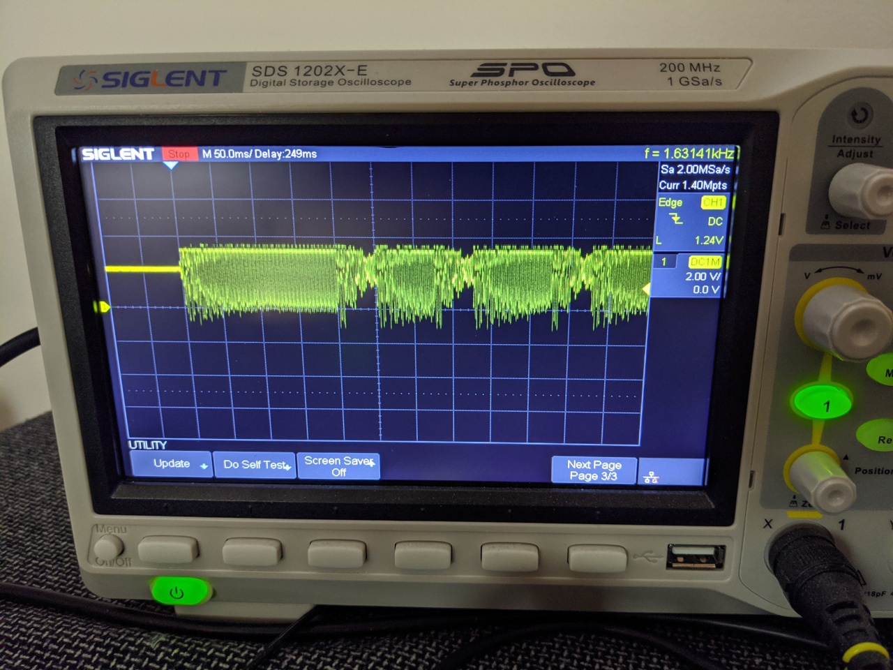
Below is a view of the oscilloscope with the probe just after the second opamp, showing the input signal going into the LM567 (not the same run as above):
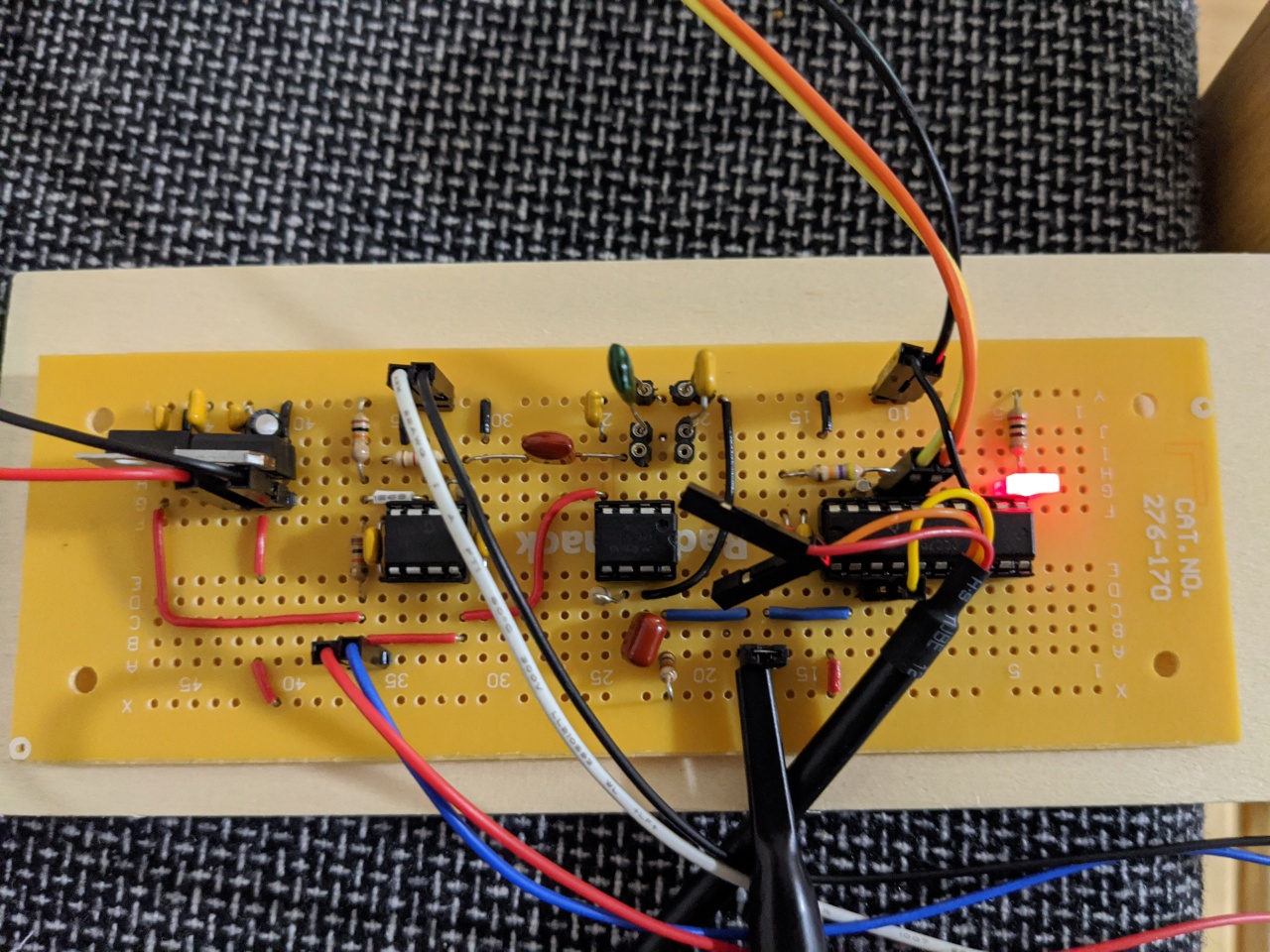
This is a close-up view of the receiver board. On the far left is the MCP607 opamp set to multiply the input signal by 10. To the right of that is the LM567. I used some sockety things for C2 and C3 so I could change the values to fine-tune the system. To the right of that is an MSP430G2553.
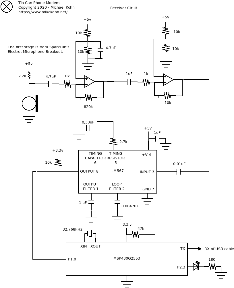
Here's the schematic for the receiver. I didn't do the transmitter just because it's pretty simple and I doubt anyone would find it useful.
Source code
tin_can_modem_receiver.asm
tin_can_modem_transmitter.asm
The source code is a little messy since I kept a lot of debugging code in it. Both the MSP430 and ATtiny2313 code assemble with naken_asm.
Copyright 1997-2026 - Michael Kohn
