PANCAKE-ROM
Posted: February 19, 2017
Introduction
Welcome to the second installment of "Cooking With Kohn" (the first being the Remote Control Food project). In this segment I'll be taking a project I posted a while ago called PAPER-ROM where I read data stored on a circular piece of paper similar to the way a floppy disk works but this time using a Swedish pancake marked up with chocolate. The one rule of this project that must be obeyed: the data disk must be edible and taste good!
The original PAPER-ROM project used an IR emitter / detector to reflect IR off white areas into a sensor while the black areas would absorb the IR. I tried using the same sensor along with an analog IR sensor for this circuit, but it seems that Swedish pancakes are not only good for storing data, but they also seem to absorb IR. Makes me wonder if there are other uses for this such as if I cover my car in Swedish pancake mix, will it become stealth to police speed traps? Or maybe fighter jets can be covered in it to confuse heat seeking missiles. Anyway, I ended up using a light to voltage sensor instead. I also decided to use a W65C265SXB board for the main CPU... if the 6502 was good for a 1541 diskdrive, the 65C816 must be good for pancake disks.
I decided on using a Swedish pancake (or what the marketing team will be calling SPT -- Swedish Pancake Technology) for this instead of an American style buttermilk pancake because Swedish pancakes are thin, don't puff up with airpockets (that to me seemed like they could read back as noise to the sensor), and they are easier to cook without browning. Dom också smaker mycket gott :).
The PAPER-ROM project ended up being really easy. From what I remember it was just a couple nights after work to create a C program to draw the disk, build the box, and write the AVR firmware. It came together really fast. This one was a total pain since there were so many variables: the height of the light sensor to the surface, the lighting in the room, the brightness of the white LED, how the LED points towards the pancake, the consistency of the surface of the pancake, smearing of the chocolate, and on top of all this the pancake dries up (starting at the edges) as it sits which causes it to "unflatten" and become uneven. I pretty much had about 4 to maybe 8 hours after making pancakes that I could actually use it before it became garbage.
Below there are two videos the first showing the circuit reading two different pancakes and the second is a montage of what it took to make the pancakes. There is also full explanation and source code that can be assembled with naken_asm.
Related Projects @mikekohn.net
| Storage: | Tape Data Recorder, PAPER-ROM, PANCAKE-ROM, LEGO Storage |
| Food: | RC Food, PANCAKE-ROM, Cyborg Chicken, Cyborg Lobster, Edible MIDI Keyboard |
Videos
This is actually two videos concatinated into one. The first part shows the 14 byte pancake being read into the laptop computer. The second video shows the 8 byte pancake. The video is unfortunately very dark because the light in the room affects the ability to read data. There are ways to take care of that but I didn't see the point in putting that kind of time into a project like this. To view on YouTube: https://youtu.be/OQv__xn9_yE
The above video is a montage of video clips showing the process I went through to make pancakes and test the circuitry. The first part of the video shows the mixing of the ingredients used to make the pancake. I should note that I changed the recipe since I shot that video by avoiding the sugar. I think it may have helped keep the pancakes from turning brown, but I could be wrong. Somewhere in the middle of the video shows the Cricut machine cutting the stencil used to put the choclate on the pancake. The last part of the video shows the sensor under an oscilloscope pointing both at pancake and chocolate. To view on YouTube: https://youtu.be/NkHAjq0PHbw
Pictures

The picture above shows the pancake with the chocolate markings sitting on top of a circular piece of cardbard (not shown in the picture). The cardboard is mounted to a continuous rotation servo motor which is mounted in a square cutout in the box. Above the pancake is a plastic straw with wires around it connected to a white LED and a light to voltage sensor. The straw is mounted with masking tape to a servo which also sits in a cutout in the box. At the bottom of the picture is the W65C265SXB board. Next to it is a breadboard with an Atmel ATtiny85 that interprets signals from the voltage to light sensor and sends the W65C265SXB board a 1 signal if the sensor is over chocolate and a 0 signal if the sensor is over pancake. A software glitch made me go with that more complex method of reading chocolate, there's more details on that in the explanation section of this page.
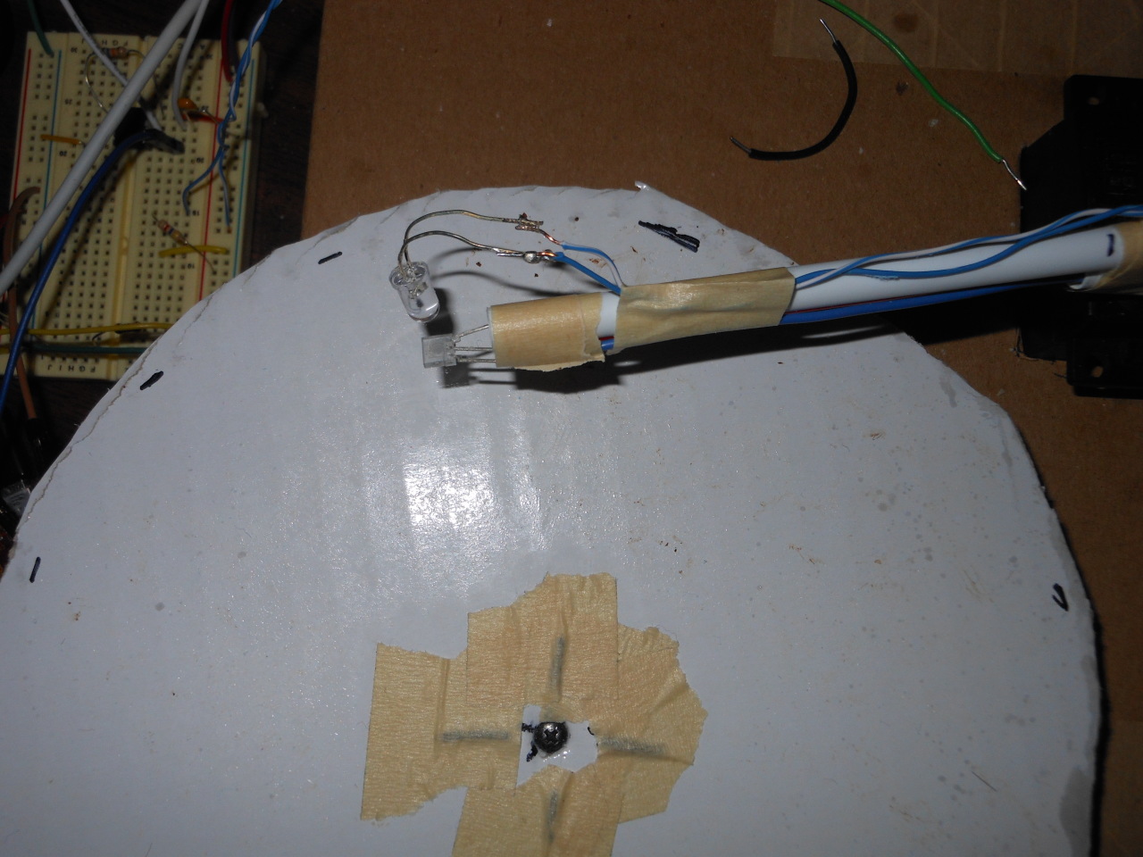
Here is a picture from the top without the pancake. The cardboard disk that holds the pancake can be seen along with the white LED and light to voltage sensor at the tip of the straw.
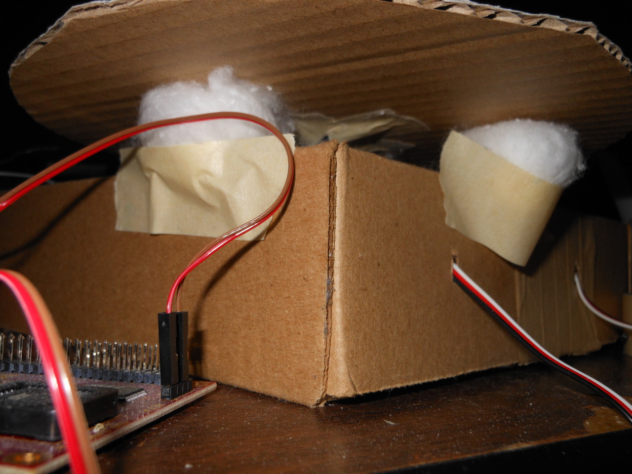
Here is a view from under the cardboard showing cotton balls taped under the cardboard disk. The cotton balls help hold the cardboard stable with (hopefully) low friction against the spinning cardboard.

Above is the .svg file (click on it to see the full image) created by the disk_spaced.py Python script. I was able to import it in Cricut's software and cut it as a stencil into poster board.
Explanation
When I originally did the PAPER-ROM project, my first thought was really to do this with a pancake, but I thought it would be that much more difficult so I went with paper. I was right... this was probably more work than was worth.
To make the pancake I originally tried a box of premade "Swedish Pancakes" mix from the grocery store, but they actually seemed more like American style pancakes just thinner.. browned too easily, fluffed up, and had air pockets (also tasted too sugary). An internet search found the mittkok.expressen.se recipe which I ended up making some changes to. First of all I didn't use salt. I also didn't use vanilla sugar and in the end removed sugar completely from the recipe. I also stopped putting melted butter in the mix and used slighty more flour. I guess in the end this should be called MSPT (Modified Swedish Pancake Technology).
To make stencils I ended up getting a Cricut machine. I created the pattern to cut using a disk_spaced.py Python script which outputs a disk.svg file. I could then import the .svg file into the Cricut software and tell it to cut it out (as shown in the second video on this page). For the stencil I used poster board which has a little bit of depth and is pretty sturdy.
To mark up the pancake I used the darkest chocolate I could find. It ends up that 2 squares of this chocolate in the microwave for 1 minute produces a nice consistency that can be spread over the stencil. If the chocolate is too hot, it will boil and pretty much ruin. If the chocolate isn't quite hot enough when the stencil is raised off the pancake, the chocolate on the outside of the stencil that should be removed will fuse to the chocolate that is needed to be left attached to the pancake. The end result being that the choclate mark will be missing from the pancake. A co-worker suggested I try "spray on" food coloring so I ordered a can of it but it seemed the chocolate was going to work so I didn't use it other than to one time test it to see what it would have been like. It actually worked *really* well except for a couple spots I over sprayed and ended up bleeding on the pancake.
For the electronics (which is actually the first thing I worked on) I started by rebuilding the platform that the servo motors are mounted to. Really the only modification I made to this was I had a circular piece of cardboard under the pancake, whereas in the original project the paper disk had a screw through it tightening it against the continuous rotation servo. In this case the pancake sits right on top of the cardboard disk, aligned by cutting out a hole in the exact center of the pancake, and held on simply by the static friction between the pancake and cardboard. I put a couple cotton balls under the cardboard platform so the pancake doesn't wobble when it spins.
So once again this project required two servo motors: one as a continuous rotation motor to spin the pancake at around 1 RPS (or maybe a little less) and one to rotate the arm that holds the sensor so that the sensor can change which track it is currently reading. The arm is made out of a plastic straw I got at a hobby store and the sensor is a light to voltage sensor (in this case it's a TSL12S-LF). I was originally just pointing this at the pancake and relying on the light in the room, but it was too inconsistent. If I got up and moved around while it was running, the amount of light it detects would change so I ended up putting a white LED pointed next to the sensor pointed at the pancake. As stated above, I also tried both digital and analog IR like the one from the PAPER-ROM project along with a color sensor. The IR wouldn't detect any change (maybe it needed to be on top of the chocolate / pancake touching it?) and the color sensor was just... not right.
At the end of the second video above, I had a pancake with with a splat of chocolate on it (as a friend of mine said when I emailed her a link to the video: "Det ser ut som att någon bajsat på din pannkaka!").. it shows the light to voltage sensor hooked up to a digital oscilloscope so I can see the voltages outputted depending on if it's over chocolate or pancake. It seemed that with the lighting in my room, pancake is around 0.8v and chocolate is more like 0.3v. So originally I was trying to get a flat 1 or 0 out of the sensor by using the emitter-base voltage (~0.6v on the PN2222) as a cutoff voltage for turning a transistor on/off. I put a potentiometer on it so I could help control it, but it was just too difficult. I ended up creating a little circuit with an ATtiny85 using the ADC with some code for digital filtering. In the end I found a nasty bug in the software running on the main CPU that it's possible this all could have just worked with the transistor and normal room lighting (a long as I didn't move after adjusting the potentiomter), but owell. I'm done with this thing...
For interpreting what was being read from the sensor I picked the W65C265SXB development board. It has a newer version of the W65C816 (the 16 bit version of the 6502 found in the Apple IIgs and the Super Nintendo) along with built in software that helped out a lot in debugging. The code I wrote is pretty simple. There is an interrupt routine that gives the servo motors the correct length pulses so the drive motor rotates at a constant velocity and the arm motor puts the sensor over the correct track at the right time. When reading each track, the software first goes through a calibration phase. It counts 128 marks figuring out how much time passed over the each mark (or more accurately how many interrupts happened) while keeping track of the longest count, which of course ends up being the track start marker. After calibrating it can assume the short marks (the ones representing a binary 0) are 1/4 the length of the start marker and the long marks (the ones representing a binary 1) are 1/2 the length of the start marker. The software calculates a threshold of 1/4 short marker + short marker to find a cutoff of what it should interpret as a short or a long. It then goes into a "read" phase where it will look for the start marker again and then read in all the rest of the marks until it finds the start marker again. There is a spot in RAM where as it reads in the data it will shift the result to the left and logical "or" in the next bit. After 8 bits, it writes out the byte over the UART to the computer.
The whole concept is actually similar to the Tape Data Recorder project which also had a start marker (as beeps instead of chocolate) along with 0's and 1's that are based on the lengths of following tones.
When I first tried spinning the 14 byte disk I was getting all garbage back instead of readable data. I then decided to drop down the density of the bits and try to do 8 bytes instead of 14. When that was reading just garbage I examined the memory in the W65C265SXB using the built in monitor software and noticed that my "variables" in my program were overflowing. I was trying to save CPU cycles by keeping the accumulator in 8 bit mode (while leaving X/Y in 16 bit mode). Unfortunately, direct memory writing was also 8 bit instead of what I assumed 16 bit. After fixing the firmware I first got the 8 byte disk working and was originally going to just stop but my curiousity got the best of me. I decided to make another set of pancakes and try 14 byte again. So I'm going to admit this.. the 14 byte worked, but really barely. It took 7 or 8 tries of making a video before I finally got it to write out my name correctly. It was, for example, writing my name as Mikhael instead of Michael or sometimes the space came out as $. So in the end the 14 byte disk is pretty difficult to repeat working.
Source code
pancake_rom.asm
line_sensor.asm
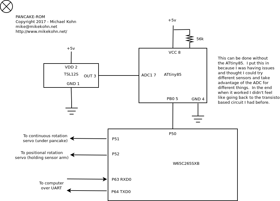
Schematic
Copyright 1997-2026 - Michael Kohn
