Cyborg Chickens
Posted: May 19, 2017
Updated: March 4, 2018
Introduction
A couple months ago I started saving bones from fried chicken I've been eating. My thought was since Wikipedia defines a cyborg as ".. (short for "cybernetic organism") is a being with both organic and biomechatronic body parts..." that if I hooked up a some motors and an MSP430 microcontroller to a bunch of chicken bones that I could create a cyborg chicken... and of course have a cyborg chicken fight.
I decided to design the cyborgs that fight to be wheeled based, but before I started working on that concept another idea hit me: could I connect the bones together so the chicken could stand (or something) with motors on the feet and arms. The first video on the page shows this chicken, which was eventually broken in half so the top part could become the red wheeled chicken. This chicken is MSP430 based like the wheeled chickens but the code on this one is written in Java. Why Java? Because it's fun to say "3 billion devices and a franken-chicken run Java".
Videos, pictures, parts list, explanation, and source code posted below.
The source code below can be assembled with naken_asm.
Update: September 27, 2017 - I moved the cyborg chicken fight circuit to a couple of dolls: Electric Cat Fight
Related Projects @mikekohn.net
| Food: | RC Food, PANCAKE-ROM, Cyborg Chicken, Cyborg Lobster, Edible MIDI Keyboard |
| Robots: | Cyborg Chicken, Apple IIe Robot, Romi |
Video
Here is the chicken that I was hoping could stand. I attached the bones together with hot glue and on the legs hinges I got at the hardware store. I used two servo motors to control the arms and two servo motors on the hip connected to the shin with an opened up paper clip. It's mechcanically flawed and didn't stand, but it looks pretty cool hanging from a guitar stand. As stated earlier, this chicken's firmware was written in Java (posted below) and after being compiled with javac into a .class file can be compiled into MSP430 assembly with Java Grinder. https://youtu.be/r7zSei_p1Xs
The video above shows the wheeled chickens fighting. At one point the red chicken freezes, this was due to the batteries falling out of the battery clip. Some masking tape around the battery clip fixed that. A second issue was the IR sensor was taped to the back of the chicken's head and the IR LED emitter I think has a fairly directed beam which meant if the controller board was laying flat, the chickens weren't receiving commands. I kind of fixed that by propping the remote controls so they were pointing upwards towards the head of the chicken. https://youtu.be/pA9melnU4_c
Update: March 4, 2018: I made a quadcopter out of chicken bones. I debated whether I should wear safety goggles or not.. it didn't hit me, but I was right behind the camera. This is an MSP430 circuit with firmware written in assembly language. I got the motors and propellers from Amazon for about $6 as a kit for fixing some Syma Quadcopter. The battery is a single cell 3.7v 700mAh Venom FLY LiPo. I used a separate coin cell for powering the MSP430 (don't ask). The firmware is set up that if it doesn't get any command for 1 second it will shut off. It wasn't fast enough for what happened though. I did get a gyro to self balance it, but I wanted to try it first without it.
https://youtu.be/siq3sI4EI4oUpdate: June 26, 2017: Added a new cyborg chicken project, this time a baseball player. A co-worker (Leland Mayron) modeled and 3D printed a baseball bat. I hotglued it to a new cyborg chicken and designed a a pitching machine based on a solenoid. The CPUs on both circuits are MSP430 and both are running code written in Java. Originally I wanted to make the solenoid "throw" the ball to the chicken, but it ended up not being strong enough. The new set up pitches upward (maybe 5 to 8 cm) and based on a 3 second delay the batter will swing. It was hitting a lot better on my workbench... almost every pitch was a pop-fly hit, but the position of the pitching machine to the chicken mattered a lot.
https://youtu.be/q7Brp6t38aYExplanation
I based this project on my previous Remote Control Food project that used a Syma S-107 remote control and a simple MOSFET circuit to drive the motors which only allowed forward wheel rotation. I wanted to use the same circuit for this one but I only had 1 remote and I think to make two robots fight they also need to be able to go in reverse. Instead of trying to fit 2 H-bridges on a circuit board I decide to just use the DRV8833 Dual Motor Driver Carrier board that Pololu offers. Really simple to hook up and saved me a ton of time soldering. Still kind of feels like cheating though.
For motors I used Pololu's 100:1 Micro Metal Gear motor and attached them to some wheels they sell. These are the same motors I used before but with bigger wheels. I also got 2 pairs of mini-servos that I originally used on the standing chicken.
The chicken bones are a mix of chicken wings and chicken legs I had been buying from the local grocery store for lunch. I washed them off in the sink using dishwashing soap and the rough end of a sponge to peal off as much meat as possible. I wasn't able to get all the meat off, which kind of gives it a neat look I think. It's dry and as far as I can tell has absolutely no smell. The bones are connected with hot glue... lots of hot glue. I did this so I could pull them apart if I needed, and I did need to do that multiple times. On the standing chicken I used some small, cheap hinges from the local hardware store to make joints. The claws are real chicken feet that I bought at a local pet store (I guess dogs like to chew on them).
The IR protocol I used is pretty simple. Like the Syma joystick, the carrier frequency is still 38kHz but instead of being 32 bit commands it's only 8 bits. By using only 1 byte, each controller should be spending less time sending data which should make transmission collisions between the two controllers happen less often. Each controller also has a different delay sequence between sending commands so if they do collide, they shouldn't as easily collide on the next transmissions. Each byte is encoded as SScccCCC where SS=01b or 10b depending on if it's controller 1 or controller 2, CCC=(0 to 5.. where 0 is stop, 1 is up, 2 is down, 3 is left, 4 is right, 5 is fire), and ccc is a repeat of CCC. If a byte reaches the receiving circuit and the motor number doesn't match or ccc is not the same as CCC, the byte is ignored. A jumper on P2.6 decides if the remote / chicken is 01b or 10b.
Issues
I hope a TI expert (employee?) reads this and sends me an email helping me out with this part. I've had several circuits now that suffer from this issue, and Google'ing for it seems to show other people have it too. When connecting my battery to my circuits they sometimes don't turn on (or really they turn on in a bad state). So my typical reset circuit for MSP430 was simply using a 33k resistor from /RST to DVcc. It seems my circuits aren't resetting properly? I put a 0.1uF capacitor from /RST to ground (yeah I know it was bad leaving that out before) and the problem seemed to stop, but then the debugger won't see the chip. I dropped the capacitor to 0.001uF (1nF like the Launchpad circuit has) and the resistor to 47k. The debugger can see the chip, but the circuit still won't turn on sometimes. I ended up fixing it by using the hardware watchdog timer. I'm actually starting to wonder if it's a DCO problem. I did try adding an oscillator fault interrupt, but I don't think that ever triggered.
Update June 27: 2017: I got a hint on a possible solution to this problem... making sure unused pins where connected properly. I looked in the datasheetfor the MSP430G2231 and the only pin I could see that wasn't hooked up was XIN... and actually in the chicken fighting circuits that pin is used to select which channel to work on. Either way on the baseball circuit I hooked up that pin to Vdd which seemed to help. But after hooking up the servos, when they moved the circuit froze. I put a 1000uF cap between Vdd and Vss to deal with that and at that point the circuit refused to turn on unless hooked up to the debugger or manually reset by shorting /RST to ground.
Update August 2: 2017: I think my new theory is that I was running the chip using the DCO at approximately 16MHz. I think what's possibly happening is the chip is running a little bit faster than 16MHz and probably becoming unstable. I've been messing with some other circuits at lower clock rates and I haven't seen the issue yet (doesn't mean it's not there).
Parts List
100:1 Micro Metal Gear motor
Pololu Wheel 40x7mm Pair - Black
Pololu Wheel 40x7mm Pair - Red
DRV8833 Dual Motor Driver Carrier
Power HD Mini Servo HD-1711MG
SB300 PC Board (for remote control circuit)
SB404 PC Board (for the chicken circuit)
TSOP38238 IR Receiver
MSP430G2231
I also got 2 Atari Joystick clones, the 9 pin D-Sub connector, and some battery packs. Oh yeah, and lots of chicken legs and wings. I got pretty tired of eating it actually... but hey, all in the name of science.
Pictures
Clicking on the images will load a higher resolution version.
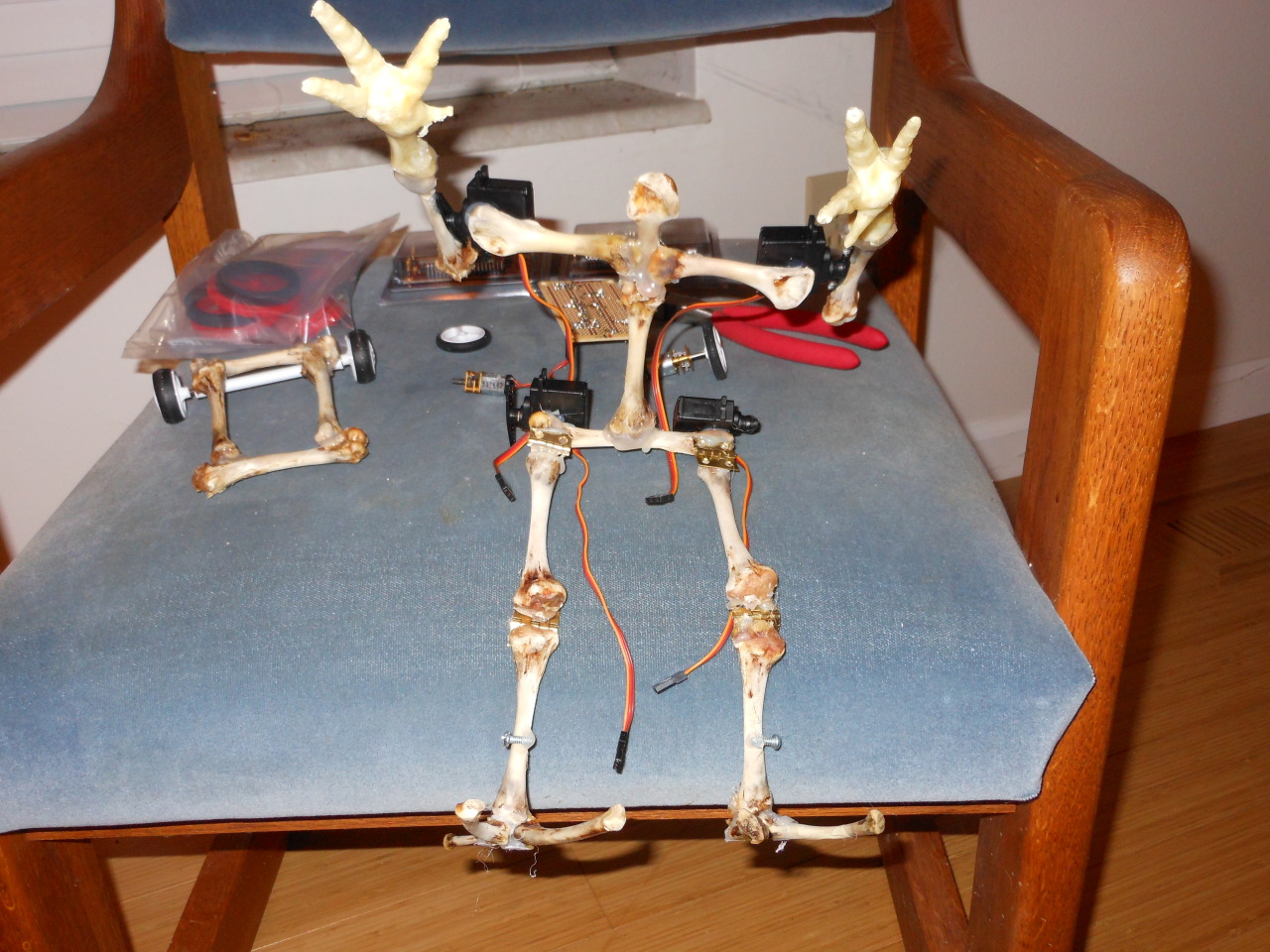
Here's the original chicken with 4 servos sitting in a chair. To the left
of it is 4 chicken legs that were the start of the red wheeled chicken.
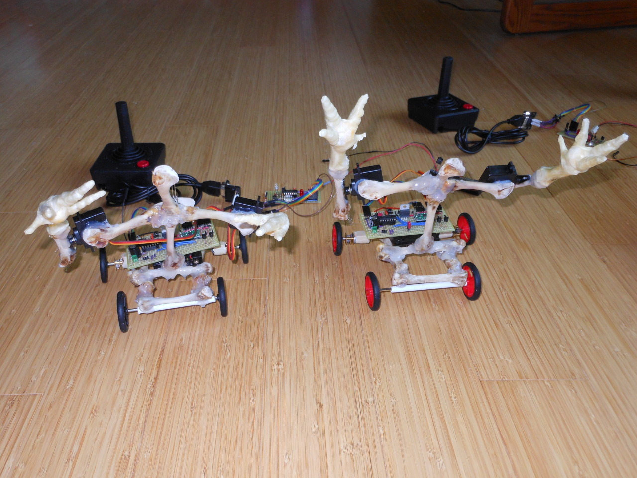
The red and black wheeled chickens posing side by side.
The motors are attached to the chicken by wrapping
masking tape hard around a popsicle stick that is hotglued to the bottom
of the chicken.

Close up of the black wheeled cyborg chicken.
The front wheels are free spinning through a thick plastic straw.
The metal axels are some Tamiya thing (I don't remember the exact thing
I got) that have a kind of flat side on them so when they are
pushed into the similarly shaped wheel the wheel can't slip. The shaft
on the Pololu motors have the same shape. Turning is done by one motor
moving forward and one moving backwards. Because the front wheels are
fixed, turning is pretty awkward and probably only works on a smooth
surface. I had to move the battery pack to the back to help the
motors with the rotation.
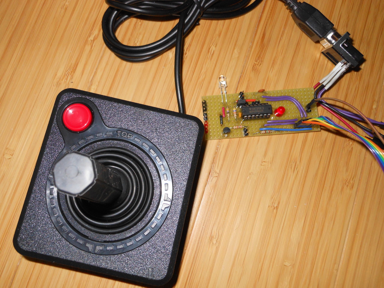
This is the Atari 2600 joystick next to the remote control circuit.
This circuit runs on two AAA batteries directly into the MSP430.
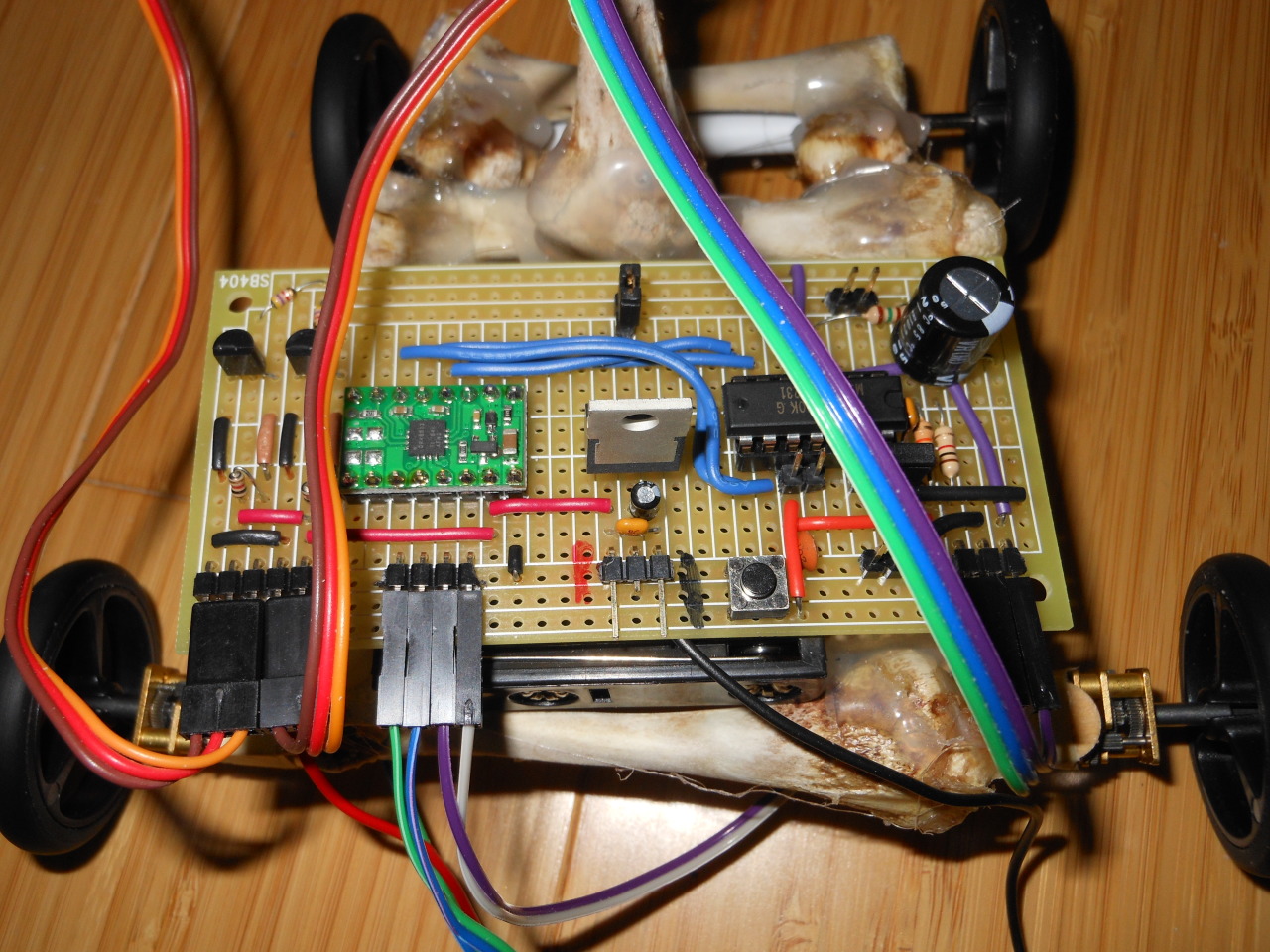
Here is a close up of the motor control circuit. The small green board
is the Pololu motor control. The boards on both chickens are identical
except the jumpers on the black wheeled chicken are black and the jumpers
on the red wheeled chicken are red. The jumpers also short out pin P2.6
differently so the software can decide which channel to use. Under
the circuit board is a 4xAAA battery pack supplying 6v to the motor
control and servos. A voltage regulator gives the MSP430 3.3v.
Source code
Chicken.java
ChickenPitcher.java
ChickenBatter.java
cyborg_chicken.asm
cyborg_remote_control.asm
Copyright 1997-2026 - Michael Kohn
