Apple IIe Robot
Posted: February 14, 2019
Introduction
This project was inspired by "scary" killer robots seen in cheesy 1980's sci-fi horror movies. In order to make the project more authentic, I started with the ultra-intimidating 6502 based Apple IIe. I started by pulling out the power supply and making a circuit that could provide 5v, -5v, 12v, and -12v from a battery and created a motor control board. The motor control board runs on an ATmega368 connected to the Apple IIe through its joystick port and includes an Emic 2 voice synthesis module. At the top is a 3D printed sword (designed and printed by a former coworker) controlled by a simple servo motor. Code running on the Apple IIe is written in Apple BASIC and sends commands to the motor control board by bit-banging data over 2 output wires from the joystick port.
This project was actually a bit harder than it looks. Some of the challenges of building this thing were:
- Creating motor control circuit that can move an Apple IIe around.
- Creating power supply replacement circuit that can run an Apple IIe on a battery.
- Figuring out how to communicate between an Apple IIe and the motor control board and writing code in Apple BASIC to send commands.
- Using the encoder on the motor's gearbox to rotate exactly (or maybe approximately) 180 degrees.
- Loading the control software on the Apple IIe.
Related Projects @mikekohn.net
| 6502: | W65C265SXB Projects, C64 Java, Atari Java, Apple IIgs Java, Tape Data Recorder, PANCAKE-ROM, Apple IIe Robot, W65C832 |
| Robots: | Cyborg Chicken, Apple IIe Robot, Romi |
Video
Here's a video of the Apple IIe rolling around my living room. Next goal is to slap a GPS on it and have it follow the Oregon trail. Just kidding. https://youtu.be/MPA4GHndOHE
Explanation
A few years ago I was trying to get rid of an SGI Indigo 2 (I had two of them that I got for free from someone) to clean out my house of computers I didn't use, so I gave one of them to one of my friends. Unfortunately, he felt the need to give me some computers in return so I ended up going home with two Apple IIe's, a Magnavox Odyssey 2, and a Commodore Plus 4. All 4 have been sitting in storage for a long time. As a side note, I do use the other SGI Indigo 2 a lot... as a foot rest when I watch TV at my computer and to brag to women hoping to impress them with my powerful obsolete computer collection.
So the first part to this project was figuring out how to run an Apple IIe on a battery. I did some research and found out the Apple IIe needs:
- +5v @ 2.5A
- +12v @ 1.5A
- -5v @ 0.25A
- -12v @ 0.25A
Ouch. I kind of assumed it would only need 5v at pretty low amperage, so now this project doesn't seem so simple anymore. When I saw this I started looking into some other 1980's computers I had laying around, but they actually seemed a bit worse. For example, the Commodore 64 wanted a 9v AC line on top of some DC lines.
I ended up finding a 5v regulator that could do up to 5A (an LM1084), but it still kind of feels wrong, especially since I'll be going from an 14.8v LiPO battery down to 5v. They usually get pretty hot when that's done. For the +12v I found an L7812CV regulator that could do 1.5A (I kind of assumed the 12v line is more for the floppy drive motor and such, which I won't have, so it probably wouldn't pull too much current anyway) and a MAX764 / MAX765 for the -5v / -12v lines. I completely removed the old power supply to reduce weight, although that really wasn't needed as shown in this video https://youtu.be/PIBHbqHjcKA which is the Apple IIe (with the power supply still inside) controlled by IR remote control. The 100:1 metal gearmotors I used are actually pretty strong.. could have maybe gotten away with some smaller motors.
This power supply worked, but not very well really. Despite the heat sink on the 5v regulator, it got HOT. So hot that after filming the video (only being on for a couple minutes) it emitted a stink of burning plastic (or electronics or something). I thought about running a 7.2v battery on just the 5v regulator, but 3 LiPOs... well, I figured for this test it only really needs to run for a couple minutes so it should be okay.
In order to drop the current draw and take some stress off the 5v regulator I ended up pulling all extra boards out of the system. This included the serial port I originally planned on using for communication between the microcontroller and the Apple IIe. It did seem to help a little at least but I needed to find an alternative for communication between the systems.
Looking for output pins all over the back of the computer and on the motherboard, I found out there is a joystick port on the motherboard that has 4 pins of output along with the regular joystick inputs. Oddly this is a 16 pin DIP socket... no idea what they were thinking on that one. I was able to write code in Apple BASIC that set these pins high / low at what I assumed would be +5v since there is a +5v pin on the DIP socket, but oddly my voltmeter and oscilloscope were showing 3.something. Actually, the Apple hardware documentation I was reading also said it should be +5v.
To write Apple BASIC code and get it running on the Apple IIe, I downloaded an emulator called linapple and wrote all the code there using a normal PC keyboard on my Linux box. To get that code running on a real machine I used a BMOW Floppy Emu which can make Apple disk images load from an SD card. In the video above when I show the source code listing, that's a video screenshot from the emulator.
I wrote some Apple BASIC code that, using 2 output pins on the joystick port, could clock out 8 bits similar to what SPI does. What's interesting is watching this on an oscilloscope, the fastest I could get the Apple IIe code to clock out 8 bits is around 300ms. Oddly, the Apple IIe hardware sets the joystick output pins high / low by doing a "PEEK" command to 2 different locations (one to set the line high and one to set it low). So to set the clock pin high my code would do: A = PEEK(49243). I probably could have made it faster by just doing: PEEK(49243), but I'm not sure I care too much about that speed.
One thing I found kind of disturbing is it appears that Apple BASIC has no bitwise operations. To check bit 7 to see if 1 or 0 needs to be clocked out next, I had to check if the data variable was bigger than or equal to 128. To do a shift left I had to multiply the data variable by 2. To mask off bit 8 I had to check if the data was equal to 256 or more and subtract 256. Commodore 64 BASIC at least had an "AND" for bitmasking.
The Apple IIe sends some pretty simple commands like, if it sends a 5, the circuit knows to say one specific thing. If it sends a 1 it knows to move foward, etc.
For the motor control circuit, I ran that on its own 11.1v LiPO battery. I did that because the motors were rated around 12v and I didn't want to try to regulate the 14.8v battery down to 12v just to run motors. On the motor control circuit I used:
- Atmel ATmega368 (not an Arduino)
- Dual VNH3SP30 (motor driver board)
- Pololu 100:1 Metal Gearmotors
- Pololu 80x10mm Wheels
- Pololu Mounting Hub
- 1" plastic ball casters (on the front of the Apple IIe)
- Emic 2 Text-to-Speech Module (for voice synthesis)
The motor control circuit uses an ATmega328 with code written in pure AVR8 assembly and I used an AVR Dragon debugger to flash the chip. I normally try to work with MSP430 chips since there are some really nice debugger tools for it, but in this case I picked the ATmega328 because of the high pin count which was needed to communicate with all the chips on the board and the fact that it can run on 5v which makes some of the circuitry simpler.
The code on the ATmega basically just listens to the joystick clock signal and clocks in 8 bits when it toggles. After that, based on the value clocked in, it will rotate 180 degrees by turning on both motors in opposite directions while counting pulses from the motor's encoders or drive both motors forward for a certain number of counts. Due to intertia and imperfections in the floor and casters and such, it doesn't always turn exactly 180 degrees. The ATmega368 can also be commanded to send text to the Emic 2 or move the servo that holds the plastic sword.
The Emic 2 is unfortunately a bit hard to understand in the video... the speaker is tiny. It has a built in amplifier, but it seemed like it wasn't quite loud enough so I connected it to an LM386. It's supposed to be saying "another visitor", "out of my way jackass", and lastly the computer make a PRINT CHR$(7) beep and the Emic 2 says "you".
In the last part of the video (and in the picture below) there are both Apple IIe's on top of each other. The reason for this was, the Apple IIe on top was supposed to be the robot and the one below was supposed to be for testing the software (since I kept the original power supply in it). So I orginally glued all the hardware to the top Apple IIe and tested it (with the heavy power supply in it) with an IR remote control circuit (Video of that is here: https://youtu.be/PIBHbqHjcKA). I then took the power supply out and tested my power circuit with a 13v bench power supply. After that I installed the SD card floppy unit on the bottom Apple IIe and wrote and tested all the software there. When that was working I moved the SD floppy to the upper Apple IIe and connected the motor control there. That computer I think had a motherboard issue cause it wouldn't read from the SD card. That computer was actually acting a bit weird before I even took the power supply out. So I ended up having to pull off all the motors and such and re-glued all the hardware to the Apple IIe on the bottom in order to make the final video.
Pictures
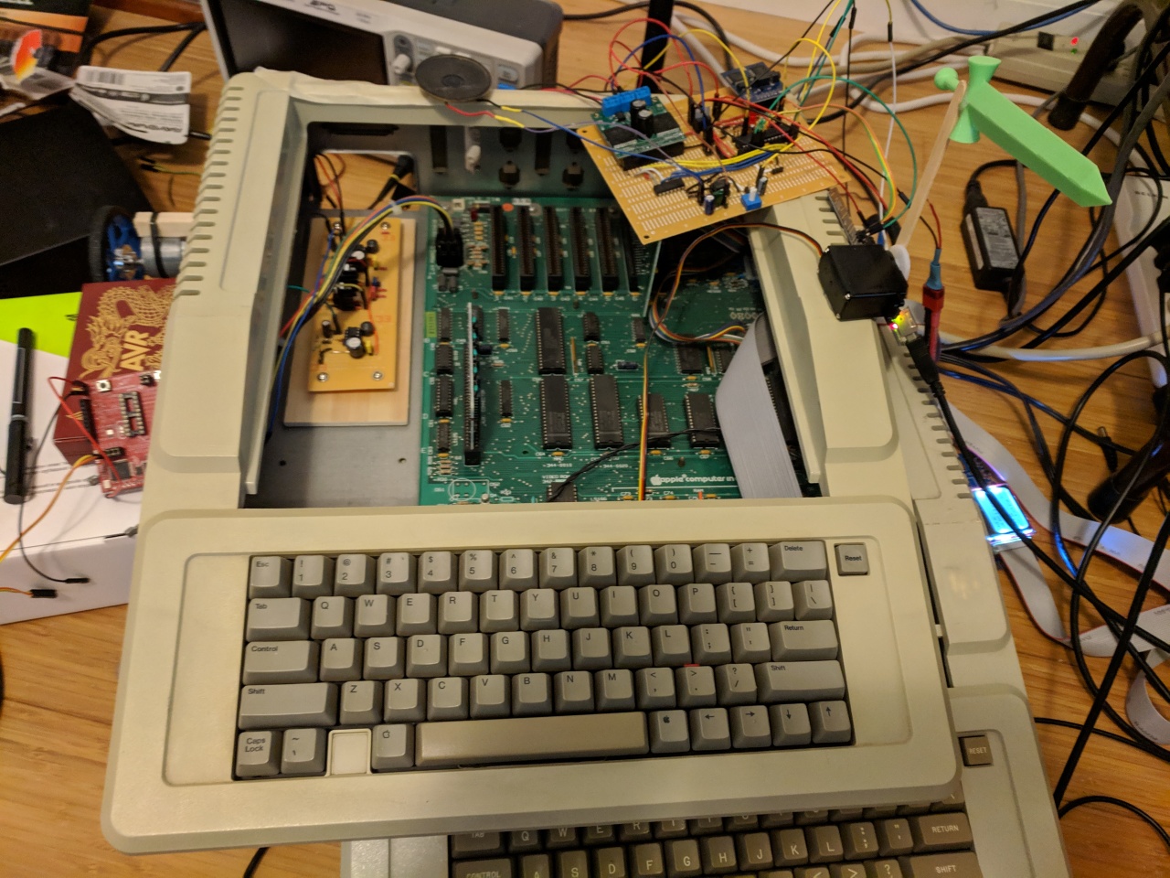
Here's an Apple IIe with motors and servo / sword hot glued to it. Inside
the Apple IIe on the left side, the original power supply has been removed
and is replaced with my power board. At the top right is the motor control
board.
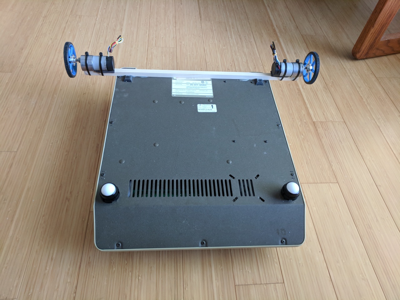
Here's the bottom side of the first Apple IIe with the motors and casters
hot-glued to it. The design is actually similar to the one I used in
the Electric Cat Fight and
Cyborg Lobster projects, except for
bigger casters and much bigger motors.

Here's the Apple IIe from the video. On the far left is a 4 cell 14.8v
LiPO battery which powers the computer. Next to it is a 3 cell 11.1v
LiPO for powering the motor control (and the motors).
I couldn't decide if I wanted to post the source code or schematics. I'm not sure there's anything too special on these circuits and drawing schematics is kind of a pain. I might do it later, but for now I want to spend my time working in some of my newer projects.
Source code
By request, here's the source code for the ATmega's firmware and
the Apple IIe disk image (the main program is called ROBOT):
apple_iie_robot.tar.gz
robot.do.zip (Apple IIe Disk Image)
Copyright 1997-2026 - Michael Kohn
