MIDI To SN76489
Posted: May 30, 2015
Introduction
After working with Java on a TI99 computer I was liking the sound of this chip and became interested in hooking up one of these to a microcontroller. The idea is to play .mid files through it similar to the Commodore 64 SID chip project I did a few years ago. Luckily arcadecomponents.com sells the TI99 sound chip, the SN76489, so I grabbed a couple. I ended up hooking up 2 of them to an Atmel ATtiny2313 (no it's not an Arduino) and two Marshall MS-2 (mini-Marshall) amps for stereo sound.
Related Projects @mikekohn.net
| MIDI: | MIDI SN76489, Edible MIDI Keyboard |
Pictures
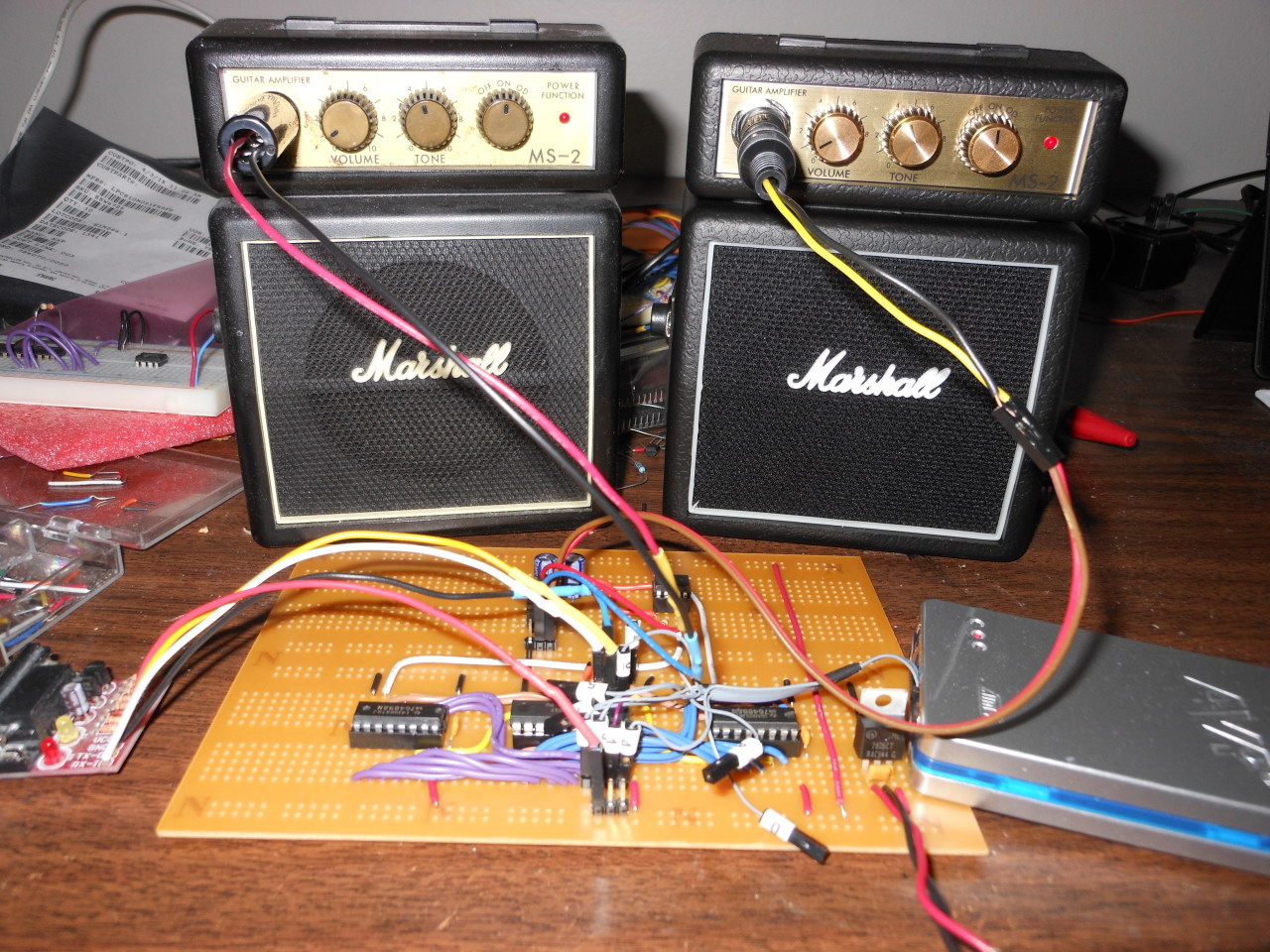
Here's the circuit board with the two Mini Marshall amps.
Samples
These are some pretty nice sounding samples. Again I downloaded MIDI
files off the Internet and played them using my player which sends sound
commands to the microcontroller:
sn76489_super_mario.mp3
sn76489_mozart_sonata_16_k545.mp3
Videos
Here's a video of the circuit playing Yngwie Malmsteen's Crying:
https://youtu.be/4_1dXztlnJM.
The song quality is partially at the mercy of the person who made the
MIDI file and a bit at the limitations of the player. In order to keep
the video from getting boring, I added a little paper cut out of Yngwie
to look at. Some of the other Yngwie stuff sounded really neat with his
complex runs (such as Far Beyond The Sun) but the rest of it didn't
come out so nice.
I also did a video (although it's pretty much just sound) of the Mozart mp3 from above (https://youtu.be/jEGN_9Q9LY0):
Explanation
The SN76489 requires 11 connections to a microcontroller. There are 8 lines which serve as a databus, 1 chip select line telling the chip needs to listen to the coming up signals, 1 line to tell the chip to read the data line, and one output signal to tell the microcontroller the last piece of data has been successfully clocked in.
I was originally going to use the ATtiny2313's internal oscillator so I'd have more free pins for signalling to the sound chip, but I couldn't get the clock accurate enough for the UART, so a 4MHz crystal was put on the board. Because of this there wasn't enough pins for the READY signal from the sound chip to the CPU. The datasheet for the SN76489 says that it will take around 32 cycles to clock in a change to one of it's registers, so that was compensated with a delay.
As I'm writing this, I'm realizing what I probably could have done is tied 1 pin from the ATtiny2313 to both write enable pins on the sound chip and hooked up both READY signals from both chips to a single pin on the ATtiny2313. The 2 pins on the microcontroller could have been used for a unique chip select.
So anyway, the signalling was done like this:
| ATtiny2313 | SN76489 | |
| PB7 | ---> | D0 (MSb) |
| PB6 | ---> | D1 |
| PB5 | ---> | D2 |
| PB4 | ---> | D3 |
| PB3 | ---> | D4 |
| PB2 | ---> | D5 |
| PB1 | ---> | D6 |
| PB0 | ---> | D7 (LSb) |
| CKOUT | ---> | CLOCK |
| PD3 | ---> | /WE (chip 0) |
| PD4 | ---> | /CE (chip 0) |
| PD5 | ---> | /WE (chip 1) |
| PD6 | ---> | /CE (chip 1) |
On the databus, the microcontroller pins are hooked up in reverse order to the SN76489 is reverse order (PB7 goes to D0 instead of D7). The reason for this is almost every CPU maker considers bit 0 to be the least significant bit. However, a lot of big endian chip makers, including 1980's Texas Instruments and IBM, for some reason consider bit 0 to be the most significant bit. Unfortunate.
The SN76489 needs a clock (up to 4MHz) to run, so I set the ATtiny2313's clock-out fuse and connected the CKOUT pin to the SN76489's clock. It ended up that at 4MHz, the lowest frequency that could be done is MIDI note 47 (123.47Hz) so I prescaled the ATtiny2313's clock to 2MHz to gain another octave of notes. I wrote a program using Google Go that converts frequencies into numbers that the SN76489 uses to represent that frequency when the clock is 2MHz. I'd normally write something like this in Python, but I wanted to try something new. Audio out on the SN76489's go to 2 opamps (dual channel MCP607's) which are then connected to two Mini Marshall guitar amps for stereo sound.
I was originally going to make the microcontroller accept MIDI commands, but I decided to optimize the command set for both 9600 and to help speed up processing for the SN76489. The first byte is the volume byte is an is encoded as follows:
7 6 5 4 3 2 1 0
1 N N C V V V V
Where bit 7 is always a 1. In the second byte bit 7 is always a 0. The two N bits tell which channel in the sound chip to use. Channel 3 actually a noise channel, but I didn't do anything with it here. The V bits set the volume where 0x0 is the loudest and 0xf is sound off. If the volume is set to 0xf only one byte is needed to be sent from from MIDI player. The second byte is simply the MIDI note tone number.
I used pretty much the same MIDI player program I wrote for the SID player and Floppy Disk Music projects. I modified it to accept 6 channels of music and talks in protocol I came up with for firmware in the ATtiny2313. The even channels are routed to sound chip 0 and odd channels to sound chip 1. The MIDI player can only play certain .mid files because of a restriction I didn't feel like taking care of: .mid files can have multiple tracks and in each track it's possible, for instruments such as piano, that the player could press multiple keys at once. Each key would send a separate note-on event and when let go each a note-off event. I was tempted to deal with this in the player, but I think for now I'll let it be.
Source code
https://github.com/mikeakohn/small_projects/tree/main/sn76489_midi
Copyright 1997-2026 - Michael Kohn
