Creating VGA Signals With Java on MSP430
Posted: August 17, 2014
Introduction
Back in 2008 I did my first few VGA projects using an FGPA with VHDL, a Parallax SX microcontroller in assembly, and then on a 20MHz Atmel AVR8 in assembly. And now it's 2014 and time to take the next challenge: MSP430 running at 25MHz. To make this even more of a challenge this will be done in Java.
So where did this idea come from? Well, one day while shopping around for MSP430's to test Java Grinder, I stumbled upon an MSP430 Launchpad based on the MSP430F5529 processor. Specs say it can run up to 25MHz which immediately made me think VGA, but the question was could I get the generated assembly from Java Grinder fast enough to draw something interesting on the display. VGA can be a challenge since at 25MHz each pixel is 1 CPU cycle when the video beam is in the playfield area. If each pixel takes 3 or 4 instructions / 12 cycles to execute, that's 12 pixels in a row that all have to be the same color.
The demo program draws 4 images on the screen each lasting for 5 seconds. The first image is a low-res Hackaday logo (hoping they would post this project :( ). The second image is the Hackaday logo again this time in higher resolution and done with inline assembly in Java. The third image is the Java logo and an MSP430 (one of my favorite micros) logo.
This project was a bit of a challenge due to the fact that Launchpad board I got had only a 4MHz crystal, so I had to use the DCO to create a 25MHz clock. The DCO's clock was really not stable enough to create an image without major jitter (as seen in the second video below) so I had to learn how to do surface mounting with a real 25MHz crystal to make this work. I should note that probably it's not that the DCO isn't a stable clock signal, but I believe what is happening has to do with the fact that the DCO is calibrated to a 32.768kHz crystal. My guess is it's pausing or changing speeds in the middle of executing code in order to keep the clock near 25MHz. I believe when I looked at hsync and vsync on the scope, the signal did appear it was accurate, it's just at a cycle level it's not.
A full explanation of how it works, along with source code so others can extend this project into something more interesting, is further down on this page.
Update 2014-March-14 - I did another project with the DCO of the MSP430G2553 that might be of interest too: MSP430 DCO.
Video
The video above shows it finally working with the real 25MHz crystal and my own circuit. https://youtu.be/OYq9yB1HFhs
And the video above shows the software running with the DCO with the original Launchpad board. Because of the way the DCO works, there is too much jitter for this to be useful. https://youtu.be/wh35CqYAFNw
Pictures
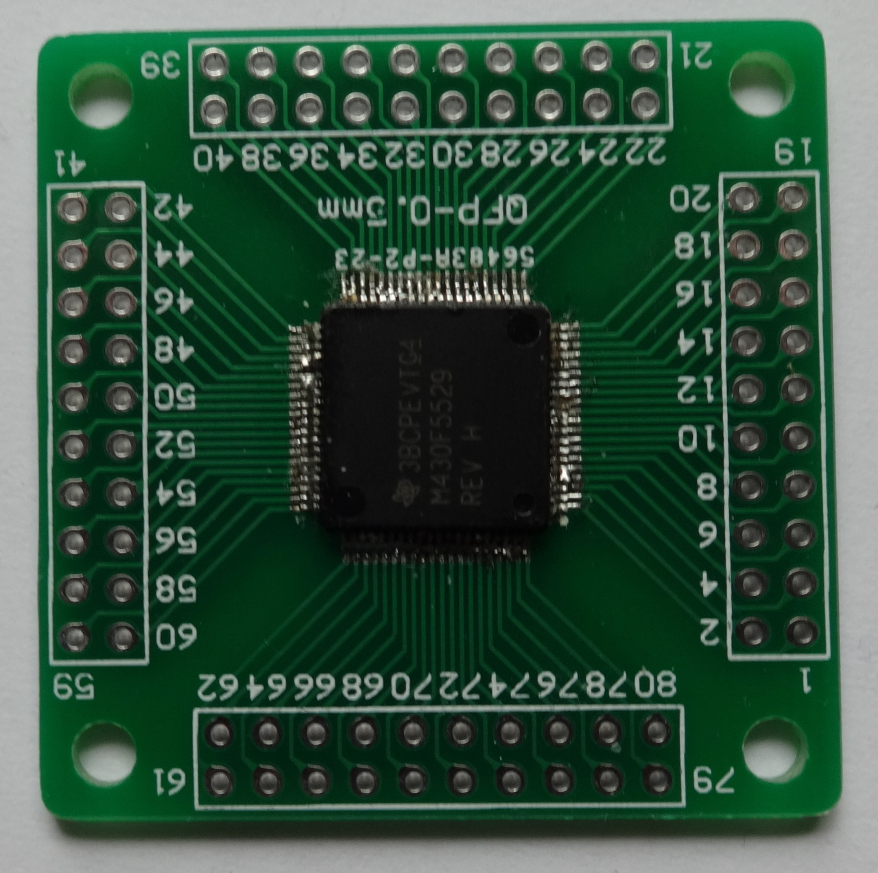
Here's my first try at SMD soldering. Messed it up :(. I used an MSP430F5529, a QFP/TQFP/LQFP breakout board, a 400W TENMA Hot Air Gun, and solder paste. I put the chip on the board, put some paste over the pins (too much paste really), and blew the hot air at it, but it didn't seem to want to melt. Maybe I wasn't doing it long enough. So I tried with a soldering iron and it melted the paste. I cleaned up any extra paste with a paper towel and any globs of solder with a copper solder wick. I looked at it under a microscope and noticed a couple bent pins touching the wrong pads.
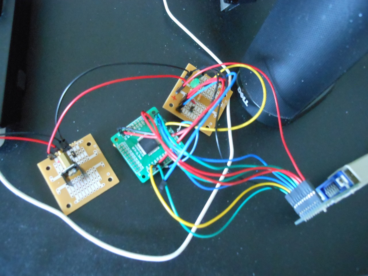
This is the new SMD board with all the capacitors (note to self: VCORE must be connected to a capacitor), crystals, and such soldered on and connected to the other pieces of this circuit. To do this one I again tried the hot air station but tried to keep it on longer. Still couldn't get it to melt so I more carefully did it with a soldering iron. I used a microscope and multimeter to find shorts and cleaned them up with a solder wick. Not the best job and still wish I could have figure out how to use the hot air station.
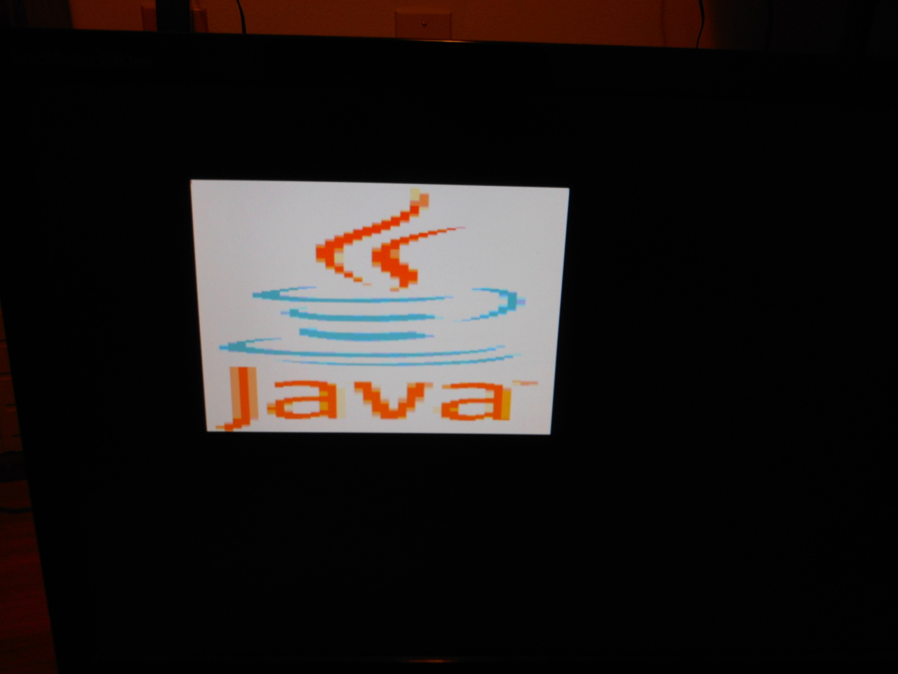
Here is the Java logo. To make these logos work with this project, I used Google image search to find and download them, then used ImageMagick to convert them to very small BMP's, and used another program I wrote to read the BMP's, pick from the palette of 64 colors, and turn them into Java byte arrays. Each array went into its own class file.
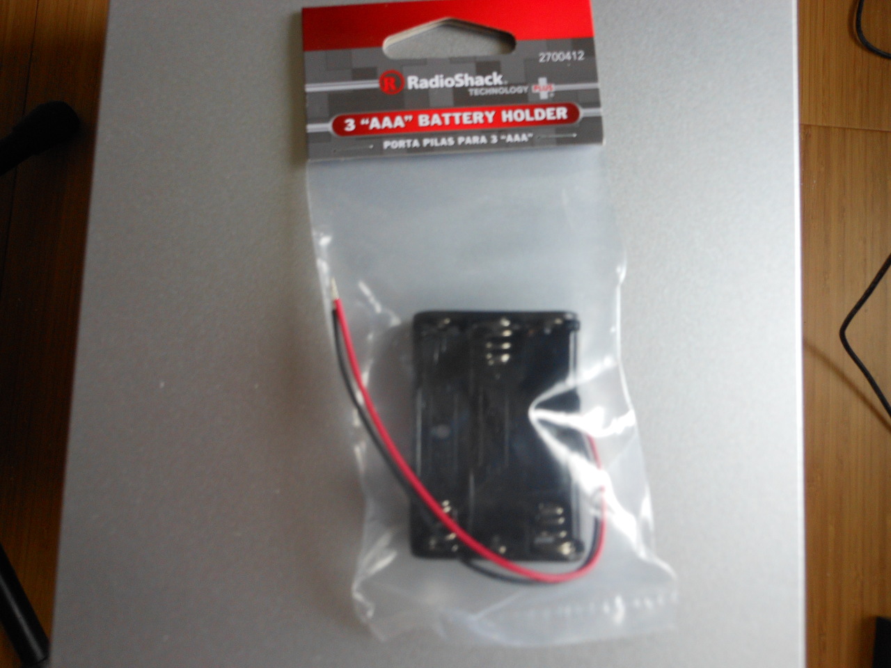
Here's a battery clip that I bought from RadioShack as a sympathy purchase. I don't really need it for anything, but I bought it anyway because I feel sorry for the store.
How VGA Works
So it might be good to start with an explanation of how VGA works. Basically, there are 5 important signals: hsync, vsync, red, green, and blue. Even though the display that the user sees is 640x480 pixels, this really needs to be thought of as a 800x525 display. Actually, this project is 800x521. VGA is pretty forgiving about things like this so it kind of doesn't seem to matter. So 800 pixels * 521 lines * 60 frames per second is: 25,008,000 pixels per second. Approximately 25MHz. Every tick of the 25MHz clock is 1 pixel, hence it's called a pixel clock.
So the first thing that needs to be taken care of is the horizontal sync.
As the video beam moves from left to right on the screen there will be:
  // 8 pixels front porch
  // 96 pixels horizontal sync (Hsync signal applied)
  // 40 pixels back porch
  // 8 pixels left border
  // 640 pixels video (RBG signals can be non-zero here)
  // 8 pixels right border
Actually, I found VGA to be pretty forgiving about this too. It seems
the video could be 96 pixels horizontal sync first and end with the front
porch. Anyway, during the 96 pixels of horizontal sync, the hsync signal
from the VGA cable must be low. Also, the RGB values cannot be anything
but 0 unless the video beam is in the 640 pixels video area.
As the video beam moves one line down, the following occurs:
  // 2 lines front porch
  // 2 lines vertical sync (Vsync signal applied)
  // 25 lines back porch
  // 8 lines to border
  // 480 lines video (the RGB signals can be non-zero now)
  // 8 lines bottom border
During the 2 lines of vertical sync, the vsync signal is held low, for the rest of the time it's high. The RGB signals must be held low unless the video beam is in the 480 lines of video stage.
As a side note, my other VGA projects were done with reverse polarity on the hsync and vsync signals: I held them high during the hsync/vsync stages and low otherwise. VGA was again very forgiving and didn't care. Even on a real CRT.
VGA.java
This code was originally written to be run on Texas Instruments' MSP430F5529 LaunchPad. I didn't feel like soldering up another VGA connector so this time I bought a Parallax VGA board. It's basically just a 15 pin VGA connector along with all the resistors needed and some debug LED's. The board has 2 bits per color component so this gives 64 different colors (6 bit color) that can be used.
The code is written in Java and compiled with javac as normal. The class files are then compiled further into MSP430 assembly using Java Grinder (check out that page for a cool Java on Commodore 64 demo too :)). To make this work I had to add support for MSP430F5529, which was mostly just being able to set the DCO to 25MHz (and later the ability to use XT2). I also added support for timer interrupts by creating a TimerListener interface. To get the resolution higher I also added an inline assembly method to Java Grinder's CPU class. More on that later.
VGA.java implements the TimerListener interface and the timer module is configured to interrupt every 800 cycles (the length in pixels of 1 scan line). The CPU cycle counter in naken_asm was quite helpful in figuring out different latencies in the code. For example, I could see every interrupt had something like 23 cycles of setup code before the interrupt even started. I could also approximate that for (a = 0; a < 7; a++); would generate about 96 cycles for the hsync signal.
The biggest challenge is drawing the pixels on the screen. Each CPU cycle burned is 1 pixel on the screen so in order to draw a higher resolution image on the screen, the code must be as optimized as possible. So what are some tricks I did to optimize? Well first, the most intuitive way to loop 40 times to draw 40 pixels is to do a simple for loop such as for (a = 0; a < 40; a++). But this does a couple things to the outputted code. It starts with setting 'a' to 0 and at the top of the loop does a compare instruction with 40 and jumps out of the loop if a is equal or bigger. At the bottom of the loop it increments 'a' and jumps to the top of the loop. It ends up that starting 'a' at 40 and doing a do/while loop removes an instruction or maybe two. When 'a' is decremented, it automatically sets the status flags in the register and in this case only the zero flag needs to be checked. The compare instruction goes away. Also, an extra jump instruction is removed. Only the conditional jump at the bottom is needed.
I was looking into more ways to optimize, mostly on the Java Grinder side, the thinking being that maybe I can figure out that I'm in a loop that only has one array varible that's getting incremented by 1 every time and just point to the start area outside the loop and increment the pointer instead of recalculating it. Kind of like the different between array[index] and array += index; array++; in C. CPU's like x86 have instructions to deal with array[index], but instruction sets like MSP430, not so much. Anyway, I decided to instead add an inline() instruction to the CPU class and draw a couple images with inline assembly instead.
Source code
vga_java.zip
Copyright 1997-2026 - Michael Kohn
