Atmel ATmega168 VGA
Posted: July 17, 2008
Introduction
First I did VGA with an FPGA, then with the SX Microcontroller, and now with an Atmel ATmega168. This differs from the SX version in that I used interrupts to control the timing. Also, since this chip is 20MHz instead of 50MHz, some of the timings are not quite accurate. Seems to work fine although there is some jitter starting halfway down the screen. Could be fixable. 20MHz is pretty much a bad clock rate for VGA 640x480@60Hz since each pixel clock should be 1 tick of a 25MHz clock. A single scan line now is 800pixels*(20MHz/25MHz) which comes out at an even 640, which is good, but the hsync which should start after 8 25MHz clocks and stop after completing 96 25MHz clocks, come out to non-round numbers (6.4 and 76.8 respectively). Still seemed to work, although like I said, there is some jitter which since this is just a useless proof of concept, I don't feel like working on it any more to fix it :).
Update August 2014: I recently did a new VGA project with a better explanation on VGA: MSP430 VGA using Java
Related Projects @mikekohn.net
| VGA: | FPGA VGA, SX VGA, Atmel VGA, Propeller Poker, Nexys2, Java VGA |
Explanation
So how it works: Basically I took all the timings of the FPGA project I did and multipied them by (20/25) to get the timings for a 20MHz clock. I set up 2 interrupts. The first is using the timer compare A, I set it for 640 clocks (equal to 800 25MHz pixel clocks). This gives me pretty nice timing of when a scan line is finished. At this point the timer also resets to 0 again. I then set up interrupts an interrupt at 7 cycles using the timer's compare B. At this point I turn on the hsync pin and do some calculations on my vertical scan since I have about 76 cycles here to play with. I also tell it that compare B is now 84 clocks and change the 16 bit Z register (r30 and r31 combined) so the next ijmp instruction will jump to a different routine. The next routine is the hsync off routine which turns off the hsync, does some more vertical scan calculations and gets ready to draw the playfield. I set the Z register to point to the playfield routine and set compare B to something higher than 122 (playfield starts at 122, but I start drawing a little later to center stuff). The playfield routine draws one scan line. The scan line information is pulled out of flash which is inserted into the source code from an include file that is generated from the Python script included in the zipfile below. When the scan line is done it changes the interrupt information for timer compare B back to 7 cycles and points again to hsync on. Kind of looks like a linked list of interrupt handlers.
Pictures
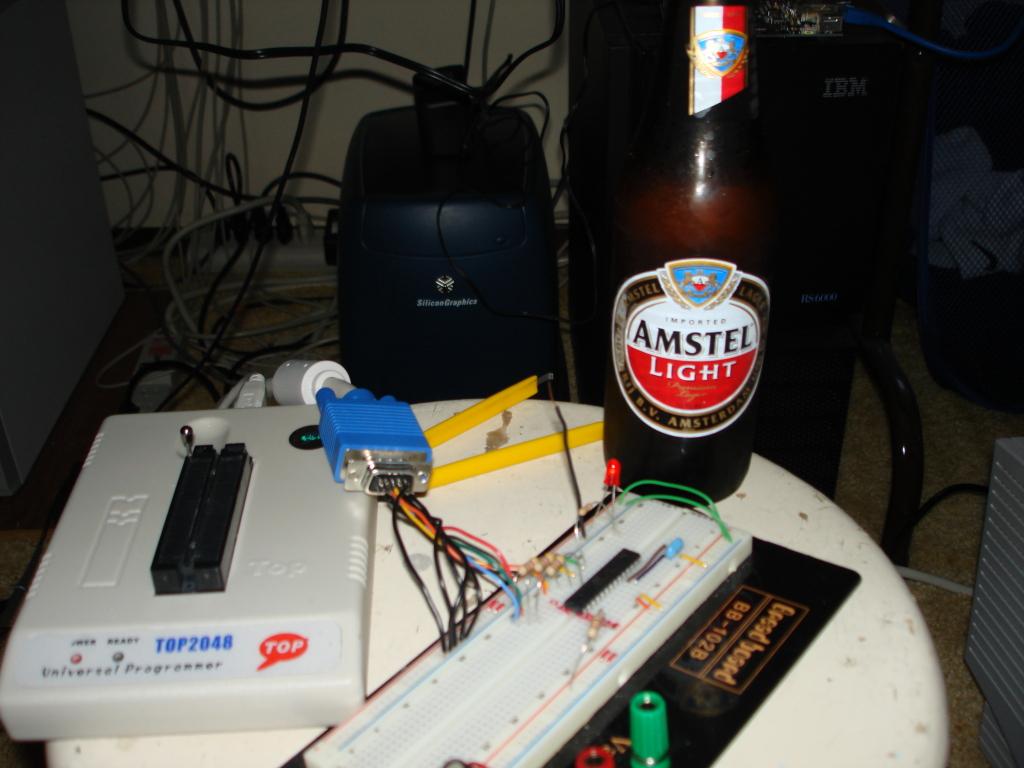
Here's a picture of the circuit and eeprom burner. The bottle there is a sign of my dyslexia. I tried to order Atmel microcontrollers and instead ended up with Amstel... HAR HAR HAR.
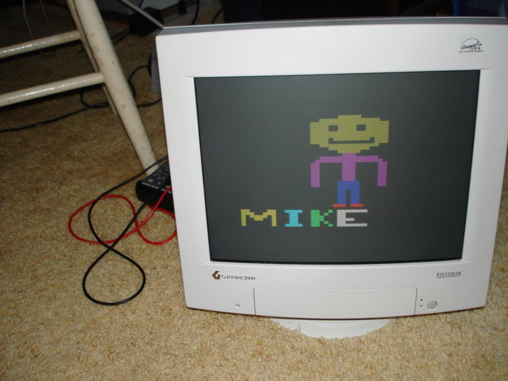
Here's a picture of the monitor with the working image. Looks like I could have worked for Atari back in 1978 :).
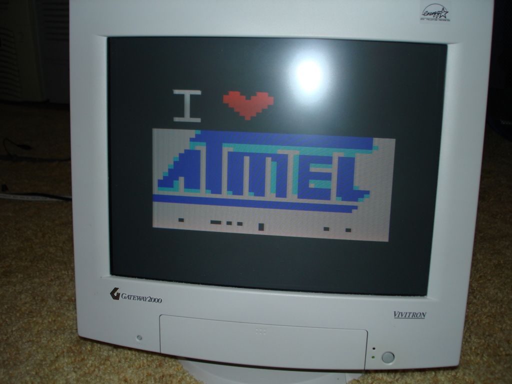
I wrote a small program to convert BMP's into the format Atmel VGA can read. I used the Atmel logo from their website and added the I <3 at the top of it. Parts of it look a bit assy at this resolution, but hey I really do love Atmel :).
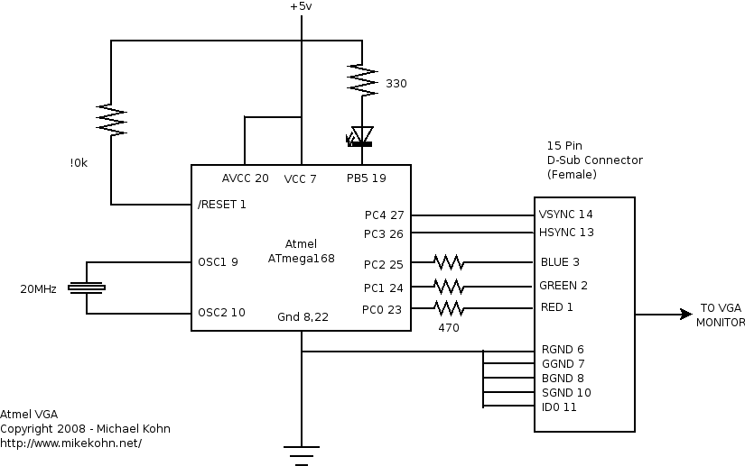
Here's the schematic
Source Code
https://github.com/mikeakohn/small_projects/tree/main/atmel_vga
Copyright 1997-2026 - Michael Kohn
