VGA Graphics Using A Parallax SX Microcontroller
Posted: June 25, 2008
Introduction
Okay, so after completing the VGA on an FPGA project, I got curious if it was possible to create VGA graphics with a simple microcontroller. Normally the microcontroller I like to use would be either an Atmel ATMega168, or better yet I thought about using the MSP430F169 since it has 2 DAC's, which would have made it possible to output shades of some colors. The problem is 640x480 (unless I missed something somewhere) needs a pixel clock of 25MHz and the MSP430 I have I believe doesn't go past 8MHz. The ATmega168 I does do 20MHz but it would end up being an odd multiple from 25MHz. The SX Microcontroller from Parallax (SX28AC/DP-G to be exact) can do up to 75MHz. So I bought one of their kits which came with a 50MHz crystal. I couldn't easily find 75MHz anywhere so I figured I'd play around with 50MHz first. Update: I did get this working on an Atmel ATmega168. Infact it works a lot better even. Click here to see what I did.
So, originally what I planned on was using the RTCC clock which counts to 255 and can trigger an interrupt when it flips back to 0. I was going to program it to count 16 cycles and interrupt. This would give me some pretty accurate timing, but very little time in the interrupt to work... I think I had a good solution for that tho. Problem was, unlike most timers in most microcontrollers, I had no way to tell it to only count to 15 instead of 255.
Btw, 16 isn't a random number I picked. Looking at the timings of VGA, the shortest piece in the horizontal scan is the front porch which lasts 8 pixel cycles (or 16 cycles of a 50MHz clock). This would also mean that the smallest block I could draw in the playfield area would be 8 pixels. Still higher resolution than the Atari 2600 :).
So anyway, I did a gross alternative which creates "artifacts" and probably isn't compatible with all monitors since I bet none of my signals are perfectly in sync. Basically I do wait loops where it checks the RTCC clock to see if it's reached a certain amount. This is so ugly since the cjb (compare jump below) instruction 1) isn't even atomic, it's more like a macro that creates 3 or 4 instructions and 2) takes several cycles to complete. If I tell it to wait until the RTCC clock reaches 10 counts for example, it could have reached 10 counts 6 cycles before my code realizes it. Oh, one other thing I did here: in order to make sure the RTCC doesn't go past 255 (since this would make all the calculations and such much more complex considering this is an 8 bit cpu and an 8 bit counter) I made the RTCC clock prescaled by 16. So every count on the RTCC clock is actually 8 pixel clocks. and 1 horizontal scan exactly 100 RTCC clocks.
Related Projects @mikekohn.net
| VGA: | FPGA VGA, SX VGA, Atmel VGA, Propeller Poker, Nexys2, Java VGA |
Pictures

This is sx_vga2.src running.
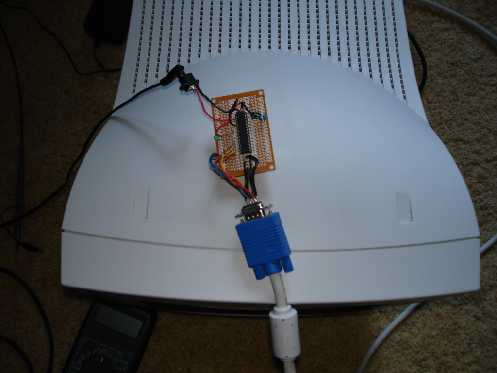
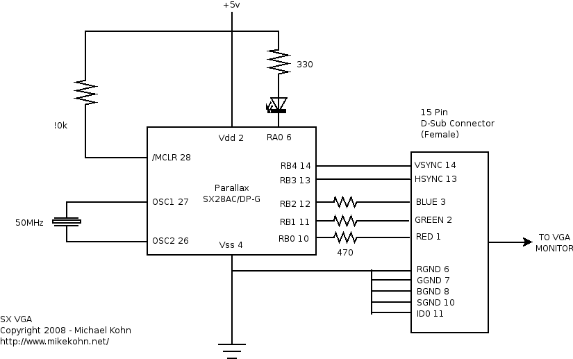
I originally used the Parallax development board to write the software and design the circuit. Since then I soldered my own circuit together. The schematic for this is below.
Issues And Improvements
Actually I believe right at line 256 (which is where my graphics start) there is a small distortion where the pixels shift a little bit. I think this is caused by the vertl/verth counter taking more cycles to compute when it vertl flips and it increments verth. I probably should have moved the graphics down by one line and avoided this area or to fix it, put some NOP's in the area to even out the number of cycles. I probably also should do these calculations in the back porch instead of the hsync section, altho there's only 80 to 96 cycles in there, so it might be kind of tight.
Another thing I noticed too while making the schematic. I took the wiring for the VGA pinouts from the Xilinx Spartan 3 FGPA schematic. Seems they hook up 5 wires to ground. I think actually one of the wires in their schematic doesn't need to be hooked up (the ID0 pin). I could be wrong tho and I haven't had a chance to remove this pin to see if I'm right.
My Opinion On The SX
At first glance, the SX chip seemed to be to be pretty much a PICMicro with some of the things I hate about that chip removed (along with some features too). First thing they seemed to do is they made the instruction set a lot more clear. I think SX code is a lot easier to read and a lot easier to program in. Also, the I/O registers are spread among all the banks. This makes it so much easier when using multiple banks, especially if an interrupt is triggered. The code it takes to save and restore a context on a PICMicro interrupt pisses me off.
Things I still ended up hating are for starters only having a w register. Atmel AVR has 32 registers (8 bit, but some can be combined for 16 bit) to play with and MSP430 has 16 (16 bit). The SX still has banking which I find to be ugly as sin, altho I can see some advanges of it too. To me it's not worth it. The SDK also only works on Windows. I program my Atmel chips on Linux. Windows is not a good development system for me. Also, the SDK is VERY buggy. The debugger didn't work at all and there was a bit that kept flipping in the FUSE setting section that messed up my crystal. To give them credit, I did download a beta version.
Actually tho, now that I'm done with this project, I rather like this chip. It's really fast compared to some others and pretty easy to wire up. I still prefer Atmel tho :).
Schematic
Source code
Actually, I probably should have cleaned the source code up a bit before putting it on the net, but owell. There's some weird stuff in it I was trying when I was having problems. Seems to work at least :).
VGA Project 1: sx_vga.src
VGA Project 2: sx_vga2.src
Copyright 1997-2026 - Michael Kohn
