Remote Control
Posted: August 3, 2009
Updated: July 28, 2016
Introduction
A few years ago I built my first IR remote control circuit based on an Atmel ATtiny13 microcontroller that could turn my Samsung TV on and off. I decided recently to revisit to project to mess with some different TV's and such. Since I already had this page written up for the original ATtiny13 remote control, I decided to update it with the new circuit and some comments on what I did wrong on the original circuit.
This page is a work in progress still..
Related Projects @mikekohn.net
| Infrared: | Remote Control, IR Guitar Pickup, Sony SIRC Infrared,, R/C Propeller RPM, IR No Fly Zone, Syma Joystick, Paper ROM, Chromebook Remote, Remote Control Food, Alexa TV Remote |
Explanation
On the original ATtiny13 circuit, I had the carrier frequency of the LED set to 39.2kHz instead of 38kHz due to some bad information I got on the net. The carrier frequiency of Samsung (and really most TV's that I've seen) is 38kHz. For information on different remote's carrier frequency, protocol, and keycodes the best place I found is the LIRC project. In their source repository they have a whole database of remotes with their protocols and key codes.
Pictures
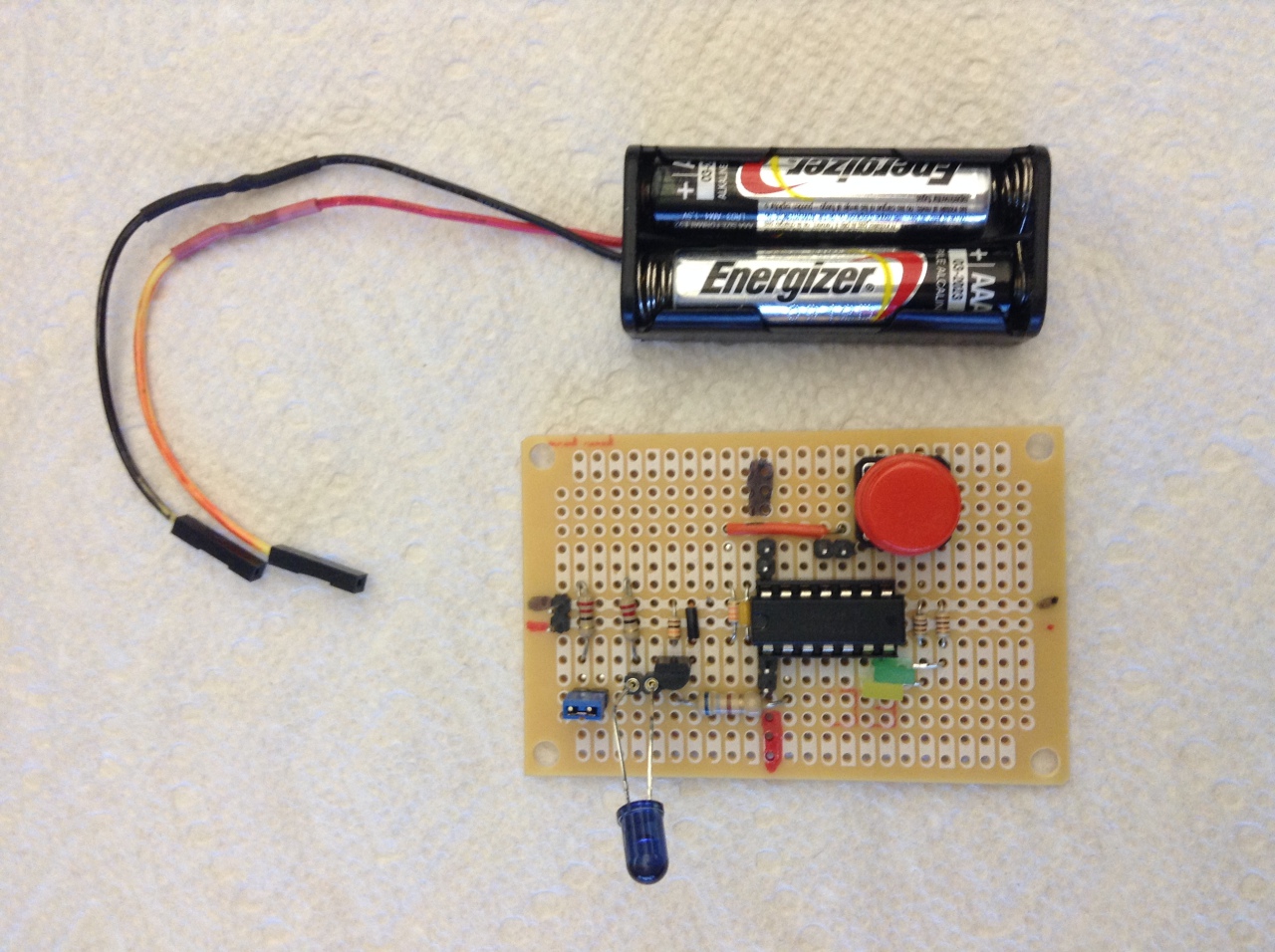
The newer universal remote control circuit with the MSP430 with a TSAL6100 IR LED.
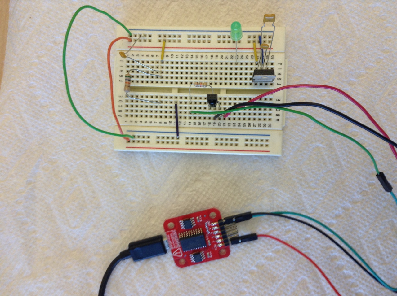
To debug the circuit I hooked up a 38kHz TSOP382 receiver to a Logic Pirate. This allowed me to push buttons on an actual remote (or the RCRN04GR universal remote pretending to be the real remote) and view the lengths of all the pulses. I also used it to confirm my circuit was putting out the appropriate pulses.
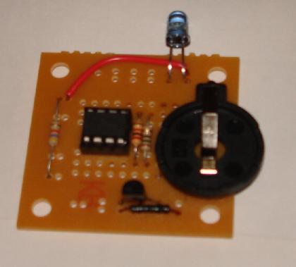
The very first remote control circuit I made.
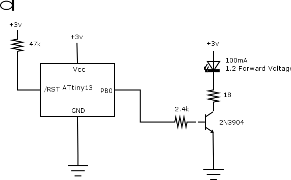
Schematic
Source code
remote_control.asm
Copyright 1997-2026 - Michael Kohn
