Brushless Motor
Posted: April 19, 2012
Updated: July 4, 2012
Introduction
I bought this Super Tigre 370 brushless (BLDC) motor back when I was working on the Linksys Quadcopter project to learn how these type of motors work, but never did anything with it. Last week I took it out and built a little circuit to see if I could get it to spin. With proof of the video below, I was successful :).
Update July 4, 2012: I have a 4th revision of the circuit now with bigger MOSFETs, faster switching diodes, and heat sinks. The Super Tigre 370 motor spins perfectly with this. Unfortunately, I used too small gauge wire for the Delta V motor and ducted fan.
Related Projects @mikekohn.net
| Motors: | Linksys Copter, Brushless Controller, IR Toy Car, Balsa Airplane |
Explanation
So unlike the brushed motors I was used to that come with 2 wires that simply applying a voltage to will cause the motor to spin, these motors had 3 wires. After searching the net and talking to people I know I finally figured out how to wire these up. It seems to make the motor spin, it requires a positive voltage on 1 wire, negative on the next, and no connection on one. After the motor turns 1 segment, the wire with + goes neutral, the - becomes + and the former no connection becomes -. After the motor turns another segment, +, -, and unconnected are rotated one more time.
So to control the polarity of each motor wire I did something similar to a typical H bridge. I used 2 MOSFETs per connection, one P-channel and one N-channel. To make a wire have a positive polarity, the P-channel MOSFET is turned on and the N-channel is left off. To make a wire have a negative polarity the N-channel is turned on and to make a wire have no connection both MOSFETs are turned off. To cause the MOSFETs to smoke and maybe cause a fire, turn on both the P-channel and N-channel MOSFET together. Okay, maybe make sure you don't do that :). A few mistakes I made while building this are I tried to run the circuit on 4 NiMH batteries (approximately 4.8v) and have the microcontroller run off the same power source as the MOSFETs. Every time I tried to spin up the motor, the MSP430 chip would reset itself. After separating using a separate battery source for the microcontroller, the power from the Launchpad kit, I was able to make the motor spin but only at very low RPM. I upgraded my battery to a 7.4v LiPO battery and the motor finally behaved. Another thing I originally left out were the pull-up and pull-down resistors on the gates of the MOSFETs. I added them actually only the N channels even though my schematic has them on the P channel also. If the gates ever get into a floating state (aka, when the processor resets and is not running any code probably) the MOSFETs could open up and start shorting current. Another thing I probably should have done is have more isolation between the motor and the microcontroller.
So the firmware I created to run the motor is fairly simple. I took the same firmware from my IR car project and removed the DC motor control part and used all the IR reading code. In the car I did the PWM to the DC motor in the main routine. In this project I'm doing the phase changing on the motor in the interrupt routine. Actually, I probably should have done the car this way :). Anyway, I made sure all the P-channel MOSFETs were on odd numbered pins and matching N channel are on the pin next to it. This gives me a truth table that looks like this:
Revision 1 of the circuit:
| P1.5 | P1.4 | P1.3 | P1.2 | P1.1 | P1.0 | Condition |
| 0 | 1 | 0 | 1 | 0 | 1 | Motor Turned Off |
| 0 | 1 | 1 | 1 | 0 | 0 | Motor Phase 0 |
| 1 | 1 | 0 | 0 | 0 | 1 | Motor Phase 1 |
| 0 | 0 | 0 | 1 | 1 | 1 | Motor Phase 2 |
| x | x | x | x | 1 | 0 | FIRE! |
| x | x | 1 | 0 | x | x | FIRE! |
| 1 | 0 | x | x | x | x | FIRE! |
Revision 2 and 3 of the circuit:
| P1.5 | P1.4 | P1.3 | P1.2 | P1.1 | P1.0 | Condition |
| 0 | 0 | 0 | 0 | 0 | 0 | Motor Turned Off |
| 1 | 0 | 0 | 1 | 0 | 0 | Motor Phase 0 |
| 0 | 0 | 1 | 0 | 0 | 1 | Motor Phase 1 |
| 0 | 1 | 0 | 0 | 1 | 0 | Motor Phase 2 |
| x | x | x | x | 1 | 1 | FIRE! |
| x | x | 1 | 1 | x | x | FIRE! |
| 1 | 1 | x | x | x | x | FIRE! |
The firmware I posted uses the Syma S107 IR remote I used for other project to control the speed and direction of the motor. To change the direction of the motor Phase 1 and 2 are reversed. To change the speed of the motor switching between the phases is done faster. The remote gives me a number between 0 and 62 or something like this for speed, so I created a look up table to translate this number into a pulse time length. I have two numbers per speed in the look-up table because I was originally going make the pulse to the motor shorter than the length of the phase. It seems like once the motor shifts to the next segment, power to the coil should be turned off since after the coil is fully on, the resistance should be quite low. Some BLDC motors have hall effect sensors to tell the firmware when to turn off, but these motors don't have such a thing.
The video below is showing the motor spinning at multiple speeds and multiple directions. It seems my fastest speed on the remote is too fast for the motor and it ends up stalling out (and making fun noises :) as demonstrated at the end of the video. [Update July 4, 2012: The stalling was due to the fact that the speed of the motor needs to be ramped up and down. I added code to do this and this problem went away]. One thing I find odd which I'm not sure is a mistake in what I've done, one of my DC motors with no load pulls very little current, however the MOSFETs on and the wires coming from the battery were quite hot even with no load. [Update July 4, 2012: I fixed the heat problem by making the length of the pulse to the motor 1/2 of the length of the phase. In other words if the motor is in phase 1 for 1ms before switching to phase 2, then electricity is only flowing through the motor's coil for 0.5ms].
The MSP430 assembly source code below can be assembled with my own naken_asm assembler.
Videos
This first video shows the motor pretty much working (with a couple stalling bugs). My latest circuit and firmware fixes all this and I have this little motor spinning perfectly. https://youtu.be/Bz6Be7-tQro
My next goal was to get this E-Flite Delta-V motor / ducted fan kit to spin. Didn't quite work :). The MOSFET's here were too small and exploded. It left a big hole in the MOSFET and I found pieces of a couple of them on the floor. I also lost a pair of underwear in the process (just kidding). Actually, the popping sound was a lot more dramatic in real life than it was on the video. Quite loud. It isn't visible in the video, but the power-source was an 11.1v LiPo battery. https://youtu.be/3VyduGaUq1g
New MOSFETS and diodes. This is actually two videos put together. In the first one the motor was stalling out, so I made some changes to the firmware for the second video. Unfortunately, 22 gauge wire was too small for this motor's current draw and it created a nice flame on the negative banana plug where the solder joint was (and burnt it off). Again this was the same LiPo battery from the previous video. https://youtu.be/FPuvoUMzCW0
Pictures

Here's the original circuit board.
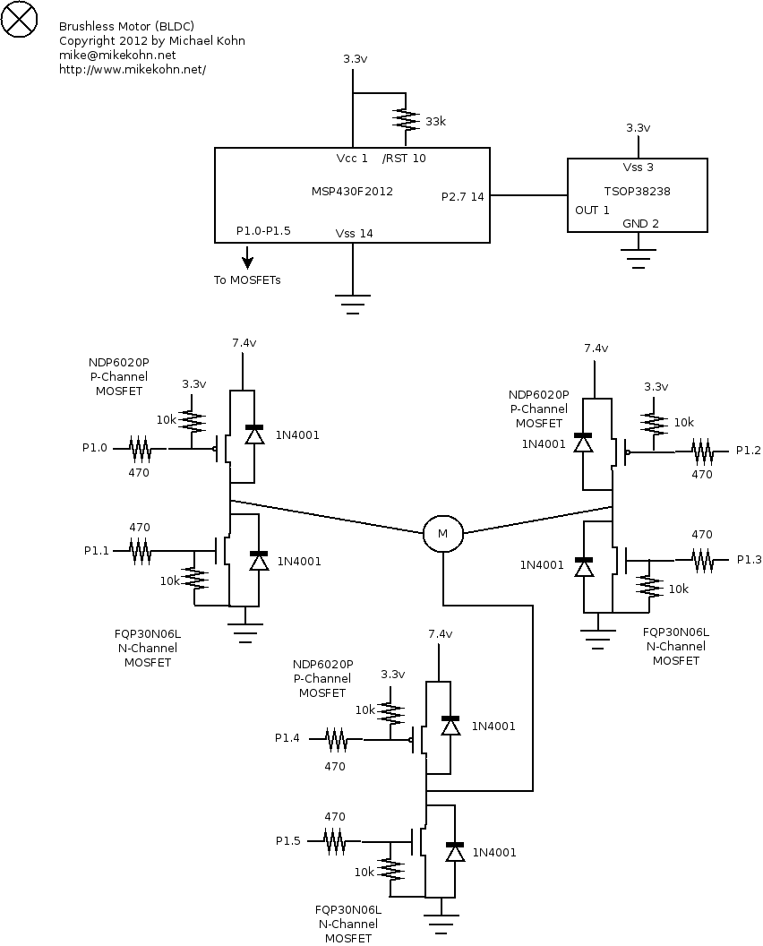
And here's the schematic of my first circuit board (must be used with brushless.asm and not brushless2.asm since the P-Channels here are active low).
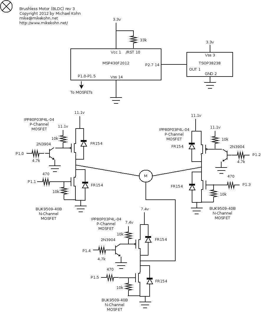
And here's the schematic of my second circuit board. This one must be used to brushless2.asm since the P-Channels use NPN transistors on the gates to allow a 3.3v micro to drive this MOSFET. This reverses the logic.
Source code (Updated June 26, 2012)
brushless_motor.asm
brushless_motor2.asm
Copyright 1997-2026 - Michael Kohn
