Linksys Coptor
Posted: August 21, 2008
Updated: December 21, 2010
Introduction
So using my Atmel Pilot firmware and software around it, I wanted to build something that could fly from it so I decided to build a quadcopter made out of a Linksys router. Using the Linksys router all the commands to the micro can be done over TCP/IP with the Naken Web webserver. For more information on how this system works, take a look at the Atmel Pilot web page. There is an explanation of the system with a diagram and a video of it working.
Update October 18, 2013: I actually started a version 3 of this project with some major improvements. I haven't had much time to work on it though, but I plan to finish it soon.
Related Projects @mikekohn.net
| Motors: | Linksys Copter, Brushless Controller, IR Toy Car, Balsa Airplane |
Videos
Latest test on December 21, 2010: https://youtu.be/n2HySJHhT6M :(. Well, at least it got off the ground.
Latest test on December 20, 2010: All motors are working. This video shows the router can lift up (tied to a table with string so if there is a problem it can't get away). In the first part, I'm moving the joystick to test that motors are slowing down to control it. Each motor has a speed value from 0 to 20. When I tilt the joystick it subtracts between 1 to 3 values from 2 motors depending on how hard the joystick is tilted. In the second part, the back of the router drops because one of the motor cables fell out :(. https://youtu.be/KlAYe0OsJM4
.
November 19, 2010: https://youtu.be/la2J34L904A
This is the original yellow router being tested on a scale to see how much
thrust these motors/propellers are giving. Not quite enough.
July 26, 2008: https://youtu.be/0KdkPXHDsVw This was my very first demo of the firmware I wrote to control the DC motors (and in this case a servo). This is the same joystick I used in the above videos to control the 'copter motors. The joystick is connected to a regular PC and communicates with the router over my web server.
Explanation
So basically what this is is 4 DC motors with propellers controlled by the Atmel Pilot system. The throttle control of the joystick will control the speed of all the motors together. When the joystick is tilted the speed of the motors will become uneven causing the device to tilt.
Pictures
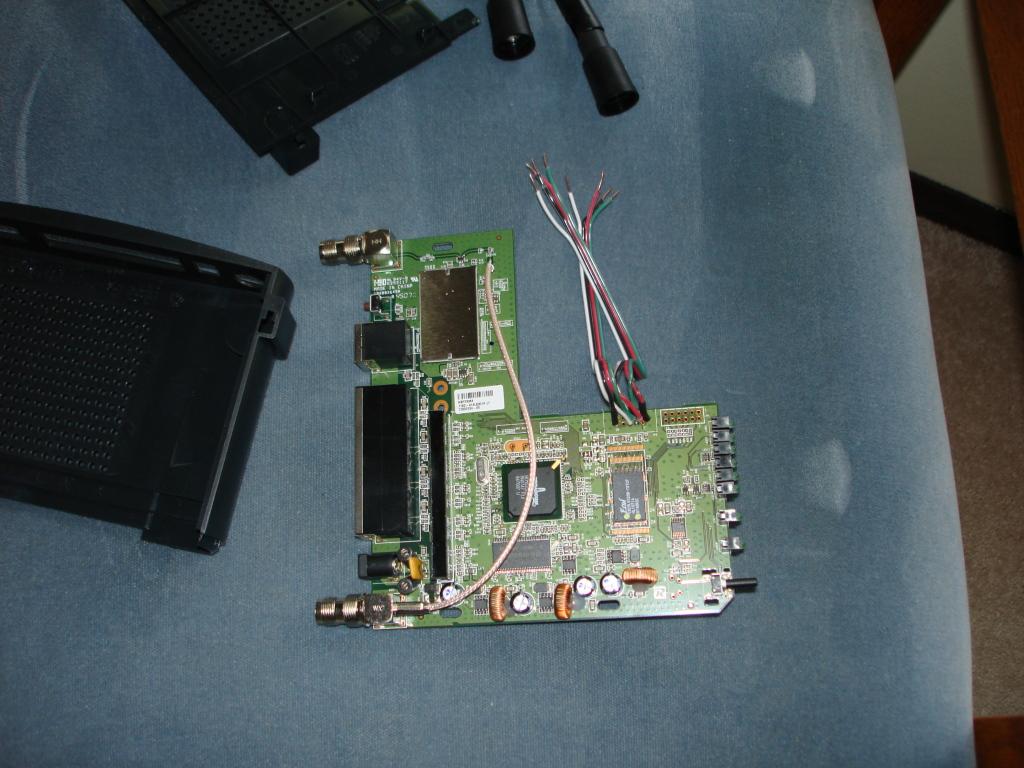
A brand new Linksys WRT54GL router with a fresh install of OpenWRT Linuxsnapped apart with UART cables solderd in. I think my warranty may be voided.
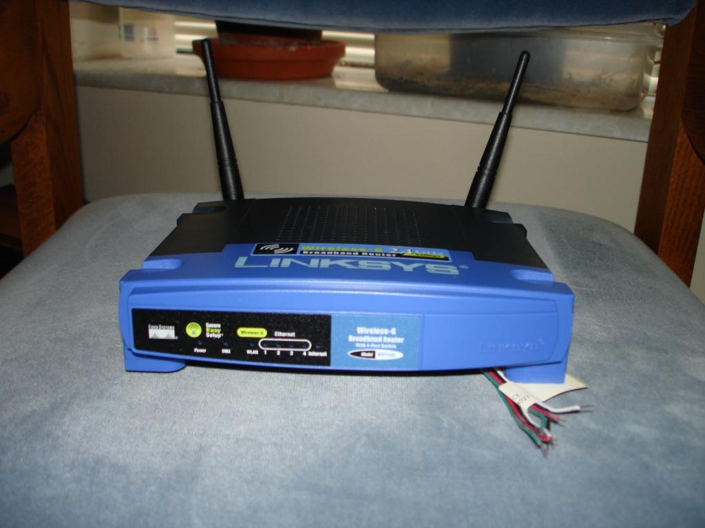
All put back together with its new dual serial ports out the bottom.

Here's the first propeller I got and motor mounted to a candle holder sitting on top of a scale. I was trying to use the scale to measure how much thrust this prop/motor combo would give using different power supplies, altho because of the way the motor was shaking, I think it may be a false test. Either way it only seemed to want to push about 25 to 50g, which isn't enough for what I need.
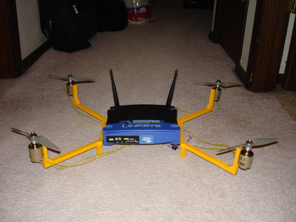
Here is the final product (before many modifications :) minus the 8 AA batteries that will go at the bottom. The frame is made out of all wood with lots of wood glue and epoxy to hold it together. Since the router was already mostly blue, it was pretty obvious I needed to paint the structure yellow so I could have my favorite color pattern: blå och gul.
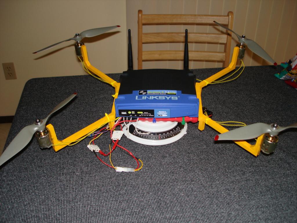
This shows the router sitting idle on a kitchen scale with the newest propellers I've been trying (bigger than the original). It's hard to tell from this picture, but the whole thing with these R/C airplane batteries (12 NiMH cells instead of the original 8 AA batteries I was using) weighs almost 1200g. I ran the router full blast and the scale dropped down to 700g showing I'm only pushing 500g.
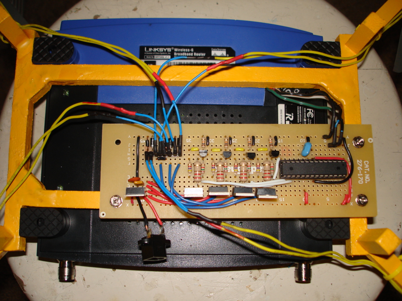
(June 28, 2009) -- So I goofed up while probing the original board with a 'scope and shorted something out which caused it to catch fire, so I redid the board a couple months ago and finally installed it yesterday trying to do a better job with the wiring and such. This circuit board has much better part placement and organization (as can be compared to the board above) so it's maybe not a bad thing this happened :).

(August 20, 2010) - The old motors are impossible to get off so I started over with a new wooden structure :(. Here are all my cut pieces of wood sitting next to my professional paint brushes I bought.
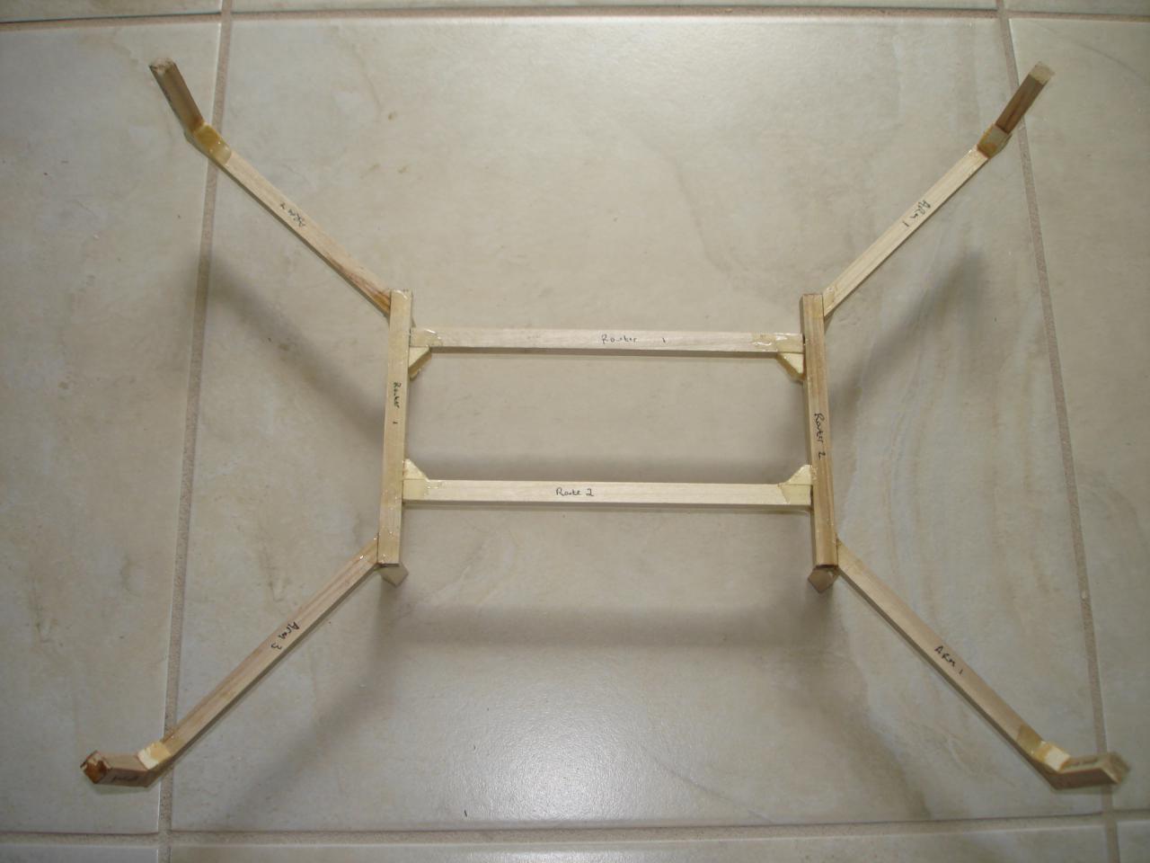
(August 20, 2010) - All glued together with some epoxy.
Dimensions:
Top/Bottom center: 187mm
Left/Right center: 133mm
Arms: 150mm (before the 45 degree cut)
Motor Mount: 50mm
Feet: 43mm

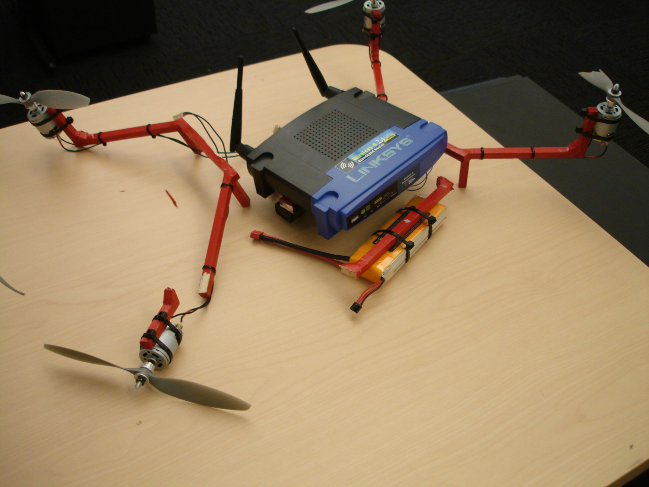
Here it is painted with the new motors and APC 8x3.8 APC SF propellers.
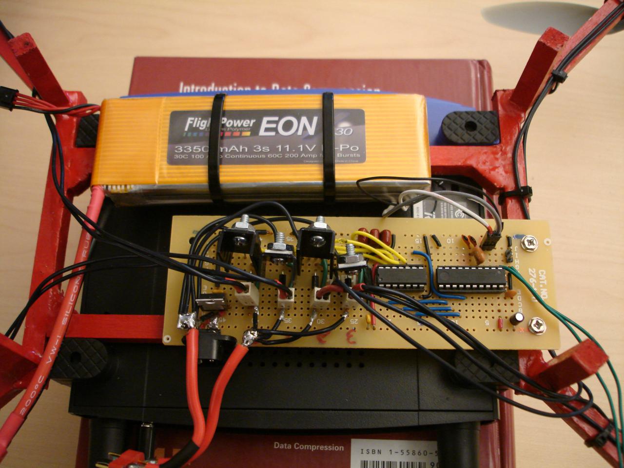
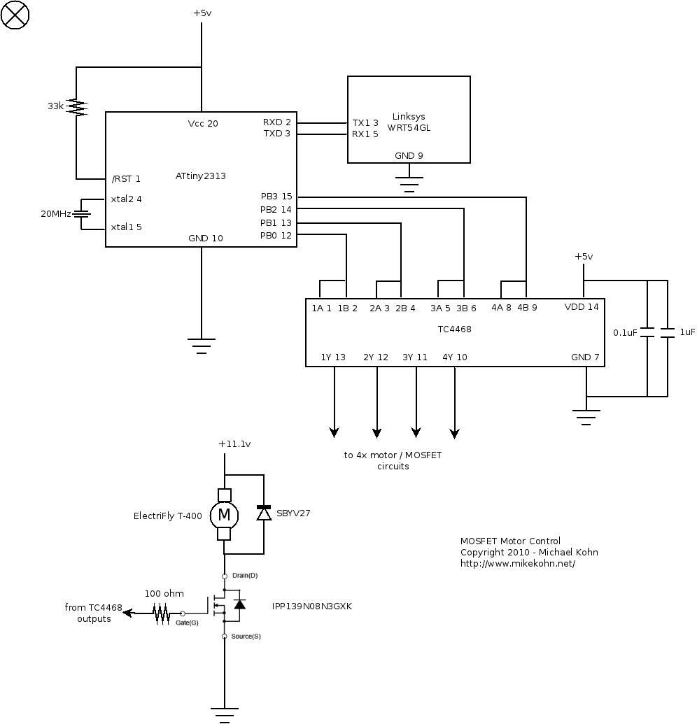
Here is the underside of the router currently. This is Rev 4 of the motor control PC board. At the top is the top is my newest battery: an 11.1v LiPo capable of putting out 100A continuous (200A pulses). On the left side of the board are the MOSFET's with the heatsinks on, on the far right an ATtiny2313, and in the center a TC4468 to drive the gates of the MOSFET's. The black wires are teflon coated wires to handle the heat :).
December 21, 2010: It did a backflip on a test flight. The video is above on this page. The wood snapped in a few places and one of the propellers snapped.
Propeller Thrust Calc
The following sites have some pretty nice thrust calculators which appear
from my testing with a kitchen scale to be quite accurate.
www.badcock.net
http://adamone.rchomepage.com/calc_thrust.htm (looks to be gone)
I created my own IR tachometer (/micro/rc_propeller_rpm.php) to get the thrust of the props/motors.
Motor Tests
Note: None of these motors except the Radio Shack motor were rated to run at 14.8v. Testing these motors at lower voltage slowed the RPM down non-linear. So 7.4v wasn't half the speed of the 14.8v. If I can find the results of the 7.4 and 11.1v tests I'll post them.
| Hobby Name | Manufacturer Name | Voltage | RPM | Propeller | Calc'd Thrust |
| Electrifly T-400 | L-308 93378 | 14.8v | 9100 | 8x3.8 APC SF | 588.6g |
| GWS EM400 | RS-380PH 45?? | 14.8v | 8500 | 8x3.8 APC SF | 507.3g |
| Graupner Speed 400 | RS-380PH 4045 | 14.8v | 8640 | 8x3.8 APC SF | 525.7g |
| Graupner Speed 400 | RS-380PH 4045 | 11.1v | 7900 | 8x3.8 APC SF | 432.4g |
| Radio Shack Superspeed Hobby Motor |
??? | 14.8v | 5800 | 8x3.8 APC SF | 220.5g |
Materials
Yellow Copter (orig)
- 4 SuperSpeed 9-18VDC Hobby motors Model 273-256 from Radio Shack
- MJ4701 Collet Prop Adaptor for 2.3mm Shaft
- PE06055E 6x5.5E Thin Electric Prop
- Linksys WRT54GL with OpenWRT Firmware
- Atmel ATmega168, TIP42G and PN2222 transistors, 1N4001 diodes.
- Different batteries tested: 8 AA Rechargable or Throw away, 12 cell NiMH R/C airplane batteries, LiPo (Electric Flight 2200mAh, 30C, 66A continuous)
Red Copter (new)
- Electrifly T-400 L-308 93378 motors
- MJ4701 Collet Prop Adaptor for 2.3mm Shaft
- APC 8x3.8SFP Slow Flyer Counter Rotating propellers from DraganFly
- Linksys WRT54G with OpenWRT Firmware
- Atmel ATtiny2313, Infineon IPP139N08N3GXK MOSFET, TC4468 MOSFET driver, SBYV27 diodes.
- LiPo (Electric Flight 3350mAh, 60C, 100A continuous) + 9v battery for microcontroller and MOSFET driver
Approximate Weight: 1200g.
Schematic (orig):

Schematic (new):
Latest News
December 18, 2010 - The last circuit was still have problems so I made a brand new one (that board was getting all toasted from all the resoldering). There's now a separate 9v battery to run the microcontroller and the MOSFET drivers. There was then the problem still that only 2 or 3 motors could be turned on before the microcontroller reset itself. So I put 100 ohm resistors between the MOSFET drivers and the gates of the MOSFETs and all four motors turn on. Now to test software and 802.11g WiFi.
November 9, 2010 - So, since my last post on here a bunch of stuff has happened. So my first set of MOSFET's were cooking themselves from all the power going through through them so I got some new MOSFET's and some heatsinks. The heatsinks completely fixed the frying MOSFET problem. I was then having the problem that when a motor runs, the microcontroller would go into a bad state. I'd also end up with junk on the UART line. I put three 0.1uF capacitors on each motor since I read it will help get rid of RF noise that can cause radio problems. That didn't help, although it probably is required for the 802.11g to work. Finally today I rewired the ground wire from the source of the transistor to a separate ground from that of the microcontroller. This helped while there were no propellers on the motors, but after putting propellers on, only 3 motors could still run at a time.
September 15, 2010 - Over the weekend I put a new motor control board together with a new design. I'm using MOSFET's now since the new motors are going to pull more amps than the old. I changed to an 11.1v LiPo battery and 4 Electrifly Motors. After I debug this circuit, it just needs an on-off switch soldered on and it's ready to go.
August 16, 2010 - I ordered some new motors from a web site. I was looking for Mabuchi RS-380PH 3270 but the closest I could find were from a website selling .. well I guess an unknown RS-380PH model number with specs of 3-12v and RPM of 12500 which matched the Mabuchi RS-380PH 4045. The 4045 seemed to be okay so I got some. So we tested one with the 8x3.8 APC SF. Despite being in a bigger can than the Radio Shack motors, the RPM was pathetic. Only 3200 RPM compared to the Radio Shack's 5800. I guess what they say is true: it's not the size of the boat, it's the motion of the ocean.
Anyway, I'm now on a quest to find RS-380PH 3270's :(. Or any motor that can spin these props around 10,000 RPM.
August 9, 2010 - We tested 8x3.8 APC SF propellers and got up to 5820 RPM. still 1200 RPM too short of being able to lift off :(.
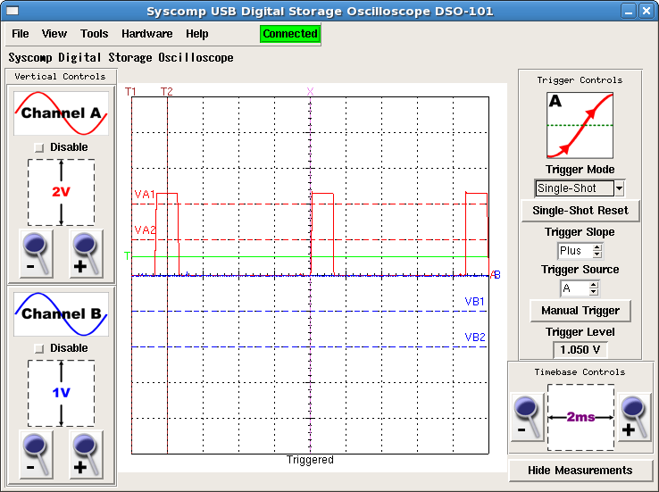
August 6, 2010 - I built a little IR circuit that while under an oscilloscope can determine the RPM of the propeller. Hopefully this weekend I'll hook that up to a micro so the microcontroller can count the RPM's, but for now it works with the scope. Anyway, with the current circuit, Radio Shack motors, and 10x3.8 APC SF propellers, one propeller appears to be spinning at around 3750 RPM.. which according to the thrust calculator from the web page above seems about right. The 8x3.8 propellers finally arrived today so hopefully we'll be testing these on Monday.
I put up a page for the propeller tachometer (schematics and firmeware) here.
Btw, here is a picture of what we got from the digital 'scope: 10x3.8 APC SF under oscilloscope. The speed was originally 8ms between peaks, but after running a little while it slowed down a little bit.
July 31, 2010 I have the ATtiny2313 firmware working now. And a new circuit built. I have 8x3.8 propellers in the mail too. Next week this will either work, or it's time to change the motors :(.
July 17, 2010 This week I finally got a chance to the test the battery. I think the circuit actually got destroyed tho (not because of the battery). Anyway it still wasn't enough to lift the thing. So I swapped out a couple of resistors and some traces fell off the board. I tried to fix that, but when I turned it on the last time, motors 1 and 4 were stuck on. After 2 min of running those motors and stopping them, they were smoking :(. So I have a few ideas what to do after building a new motor control board. First of all on the new motor control board I will an Atmel ATtiny2313 instead of the ATmega168 to save space on the board and simplify it a little. This will probably take a firmware change. Next, my current propellers are 9x6 in the back and 9x4.5 in the front. I've been discussing this with friends at work and we decided to try newer propellers with less pitch so there is less resistance against the motor. One of them found 10x3.8 props on Amazon.com so I plan on getting these. I also started looking for new motors, although I'm having trouble finding any that fit in my electrical specs. If anyone has any suggestions on propellers and motors, feel free to email me.. :).
August 26, 2009 Just wanted anyone interested to know I haven't given up. So earlier this year, I hooked up my oscilloscope to test some things (I've had a horrible voltage drop across the motors with the batteries I had.. actually with any supply I put on the circuit) and I guess I hooked something wrong and ended up smoking a transistor. There was literally smoke rising from this thing :(. So I remade the circuit, which is probably a good thing cause I did it so much nicer this time (pictures below). So anyway around May I read that NiMH batteries need to be charged and discharged a couple times before they hold their full charge so I decided to try it. I charged the two battery packs up (my 20A @ 14.4v power source) and ran the battery down (playing with the throttle a bit to test a firmware fix) until the motors just quit (the router stayed on). I did it a second time but this time just leaving it run without touching it. This time when the motors shut off, the router shut off too. I thought this was kind of weird, but what was even weirder was the hissing sound and then the horrible smell. I carried the thing to the kitchen to see that one of the battery cells had popped and wouldn't stop smoking. Being afraid the other cells would explode I took the whole thing outside and let it smoke out. Took a while. So after this incident, I cancelled the project. For about 2 hours. So I was thinking about it and wondered if my voltage drop was due to the small wires I used to connect the motors to the PC board. So I first unhooked one motor, placed a 600gram guitar pedal on top of the router to help hold it down, hooked the motor to the 15A @ 13v power supply I have in series with an ammeter and measured 4.5A starting and 4A while running. I then connected the same circuit except direct to the motor (not through the small wires) and measured the same thing. By the way, according to Radio Shack, these motors draw like 2A max :(. So I hooked up the motor with the small wires back to the power supply and measured voltage across the motor and got 13v. No more voltage drop! And btw, with just this 1 motor running at 13v, that edge of the router was picking up off the carpet. If it wasn't for the shape of the base and the 600g guitar pedal, it probably would have flipped over. Looks like I just have to figure out the reason for the voltage drop (which I'm 99% sure I know what it is now) and buy a new battery, which I found already a LiPo battery capable of 40A which I plan to buy in a couple weeks. This project may finally be flying soon :).
Download
All the software for this project is on my Atmel Pilot page.
Copyright 1997-2026 - Michael Kohn
