IR Toy Car
Posted: April 10, 2012
Introduction
A couple years ago I got this $12-$14 R/C car and did a drag racing christmas tree project. Unforunately, this cheapo car can only go forward or back at full speed so after working with my Syma S107 Helicopter no-fly zone project, I decided to "pimp my crappy-ass toy R/C car" by replacing the radio circuitry with my own circuitry using an IR receiver that understands the Syma remote IR commands. I also added headlights and purple LED under the car to make the car glow at the bottom. I used the A/B switch on the Syma remote to control if the lights on the car are on or off. The biggest negative of this remote is it only transmits if the helicopter throttle stick is forward. I ended up making it move forward and steer left/right using only the pitch/yaw (the right stick on the controller) so the throttle still has to be forward for anything to happen. Since I have my own circuitry I was also thinking about running it at a higher voltage than the 4.5v of 3 AA's, but since there isn't any room for extra batteries in the car I decided to stick with 4.5v. I may mess around with this later.
Related Projects @mikekohn.net
Explanation
The circuitry is pretty simple, although it was quite the bitch to wire it up mostly because I wanted everything to fit in such a small area so it would all fit in the car. My chip of choice here is the MSP430F2013, not for any special reason but because I had one laying around. This chip can be replaced without any circuitry or firmware changes with MSP430F2012, MSP430G2231, and probably a bunch of others. The drive motor is controlled by 4 MOSFETs (NDP6020P and FPQ30N061) in an H-Bridge configuration and the steering motor is controlled by ZTX1049A (NPN) and ZTX1149A (PNP) transistors also in an H-bridge configuration. My original plan was to only use ZTX1x49A's in both bridges, but it ended up that I would need some extra circuitry on the PNP's since I wanted to run the bridge at 4.5v and control it with 3.3v and I didn't think I would have space on the board for it. In the end I regret it since I did have the space for it and the MOSFETs are quite tall and heavy :(.
I had to do some plastic mods to the car itself. Where the headlights are now there were a couple clear plastic tabs. I removed the tabs and carefully bored a hole by twisting wire cutters where the tabs snapped into place. On the hood of the car, I cut open a tab by heating up a paper clip to melt the space away and using an exacto knife to clean up the area. The idea is to have a space for the IR sensor to be outside the car, kind of making it look like a hood scoop of some kind. Behind one of the rear tires in the frame of the car, I again melted a small hole using a hot paperclip so I could fit the purple LED that lights up the bottom of the car. In the end I also had to remove the entire top of the car and hang the electronics out the top :(.
The firmware is pretty simple. The main code spins while polling the IR sensor and pulsing the drive motor if needed. If it doesn't notice any data on the IR sensor for about 1 second, it shuts off the motors. When the IR sensor senses a pulse it reads in 4 bytes and then adjusts the headlights, drive motor control registers, or steering. One thing to be careful with, with the H-Bridge if the transistors in the bridge are turned on wrong, it will create a short and the transistors will get quite hot and could blow (maybe even start smoking :). I had this problem where when I turn the circuit on and hook up the Launchpad debugger, the pins of the MSP430 were (I believe) setup as inputs since it's in a reset state. This was putting partial voltage on the gates of the MOSFETs and made them get really hot.
Issues
So for anyone who wants to repeat this project, here are a few things I know I did wrong or could have done better. Mostly the reasons I did the things I did were because I wanted the circuit to fit inside this car and didn't have a lot of board room to play with.
- Isolotion between transistors and microcontroller.
- Use ZTX1x49A transistors instead of MOSFETs to lower the weight and make the circuit smaller.
- Pull-down and pull-up resistors on the gates of the transistors.
- I used 180ohm resistors on the white headlight LED's. Could have went as low as 100ohm with no problem and had brighter lights.
The MSP430 assembly source code below can be assembled with my own naken_asm assembler.
Video
Just a video if the car driving around. https://youtu.be/5drYAq9RP6Q
Pictures
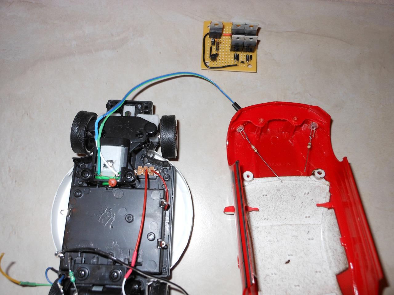
At the top is the circuit-board half done. This pic also shows the LED's installed in the headlights area of the car.
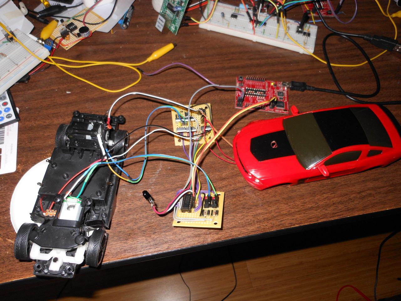
Here's the two boards fully connected with the Launchpad hooked up as a debugger.
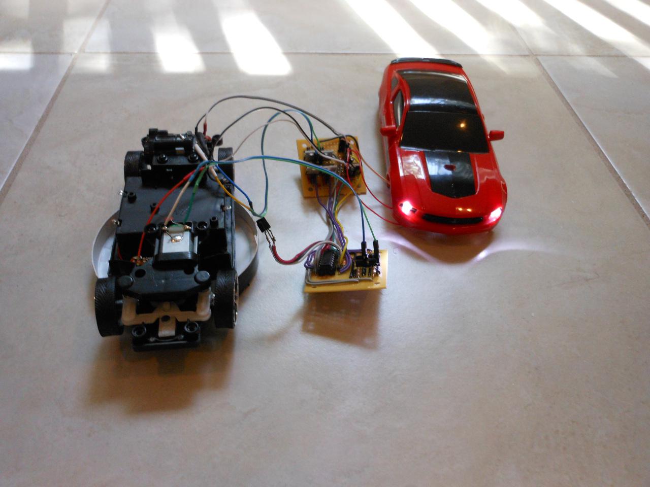
Here it is with the headlights on.
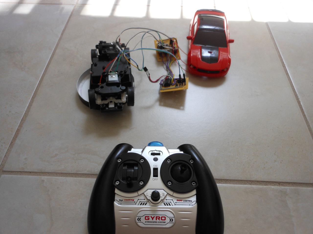
And here it is ready to go with the remote control.
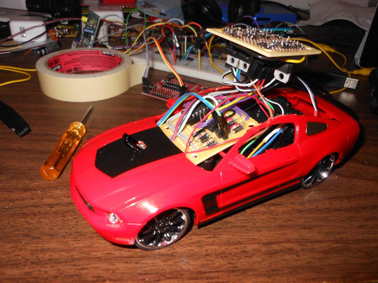
I had to cut the top of the car off for this to fit. What an ugly mess :(.
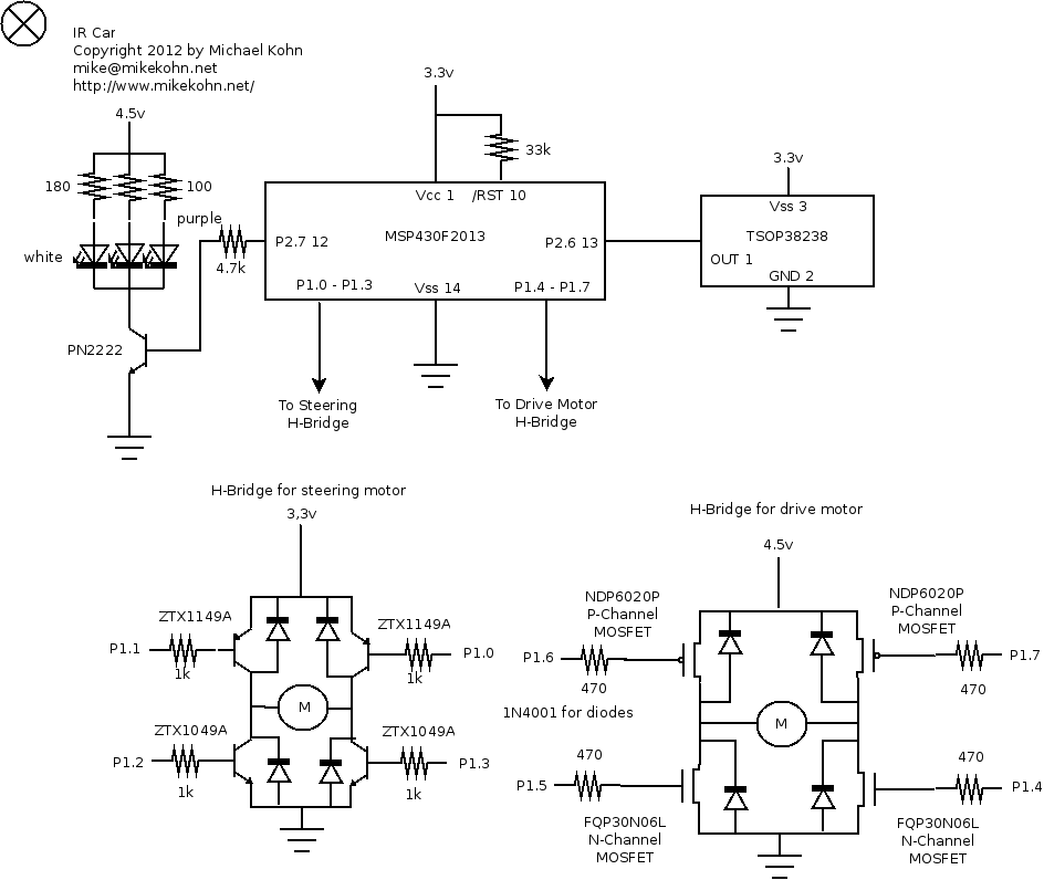
And here's the schematic...
Source code
https://github.com/mikeakohn/small_projects/blob/main/toy_cars/ir_car.asm
Copyright 1997-2026 - Michael Kohn
