LED Panel
Posted: October 19, 2014
Introduction
I got one of these Adafruit LED panels to mess around with. I think someone made an Arduino sketch or a Raspberry Pi Python library or something for it, but I'd prefer to make my own controller for it. Unfortunately I couldn't find any really good documentation that explains what needs to be done. A little playing around with it and I think I got it figured out so I figured I'd share my findings on here.
I was originally wanted to use an ATtiny2313 but I needed 256 bytes to hold a full image and I wanted to do double buffering (512 bytes total) where the ATtiny2313 only has 128 bytes. I tried to order some ATtiny4313's but nobody had them in stock. I ended up using an ATmega168 I had laying around.
Related Projects @mikekohn.net
| Artwork: | XOR Gate, Motion Eyes, WS2812 LED, LED Panel, Half Adder, Cyborg Chicken, Electric Cat Fight, Iced Electronics |
How It Works
Basically this 32x16 LED panel can be thought of as having six 32 bit shift registers. Three of these shift registers work together to hold the red, green, and blue information for one line of LED's. This means that you can really only turn on two rows of LED's on this panel at a time. If my A,B,C pins on the panel are all set low, then whatever is in shift register 0 will show up on line 0 and whatever is in shift register 1 will show up on line 8. If I set pin A high and leave the rest low then line 0 and line 8 will turn off and line 1 and line 9 will display what's in the shift registers.
So maybe a question is if I'm shifting bits into the shift register, how do I stop the LED's from displaying the bits as they are being shifted in? There are two pins used to control this. First is the latch pin. The bits won't get pushed to the output buffer until the latch pin is pulled high and then low. This means bits can be shifted into the shift register slowly but won't actually be visibile until latch pin is hit. There's also an output enable pin (which seems to be active low) so if this pin is pulled high, the LEDs will turn off.
The firmware follows the following logic:
for line = 0 to 7:

  for pixel = 0 to 31:

    set R0,G0,B0 and R1,G1,B1 from RAM

    set CLK pin high

    set CLK pin low

  next


  set OE (output enable) high - turns off all LEDs

  set LAT or STB (latch/strobe) high to copy shift register's data to output

  set LAT or STB (latch/strobe) low

  set OE (output enable) low - turns on LEDs


  pause 1.5ms

next
Firmware API
To reduce the number of bytes that have to be written over the UART the following command sequences can be used:
HIBYTE LOWBYTE COLOR           Set pixel number to color @address of hi:low
0xff                           Page flip
0xfe                           Clear drawing buffer
0xfd                           Copy display buffer to drawing buffer
0xfc                           Shift drawing buffer left
0xfb                           Shift drawing buffer right
0xfa                           Shift drawing buffer up
0xf9                           Shift drawing buffer down
To make this easier I made a Python module (included in the git repository for this) called led_panel.py. With this module I could do the above example with:
leds = led_panel("/dev/ttyUSB0")
leds.copy_display_buffer()
leds.plot(x, y, 1)
leds.page_flip()
Videos
Here's a video of the circuit running demo Python code from the git repository. https://youtu.be/ly3KT60fLSA
Here is a demo of the circuit being driven from a Tessel 2 and a node.js program. https://www.youtube.com/watch?v=-sxFe-ndT2c
Pictures
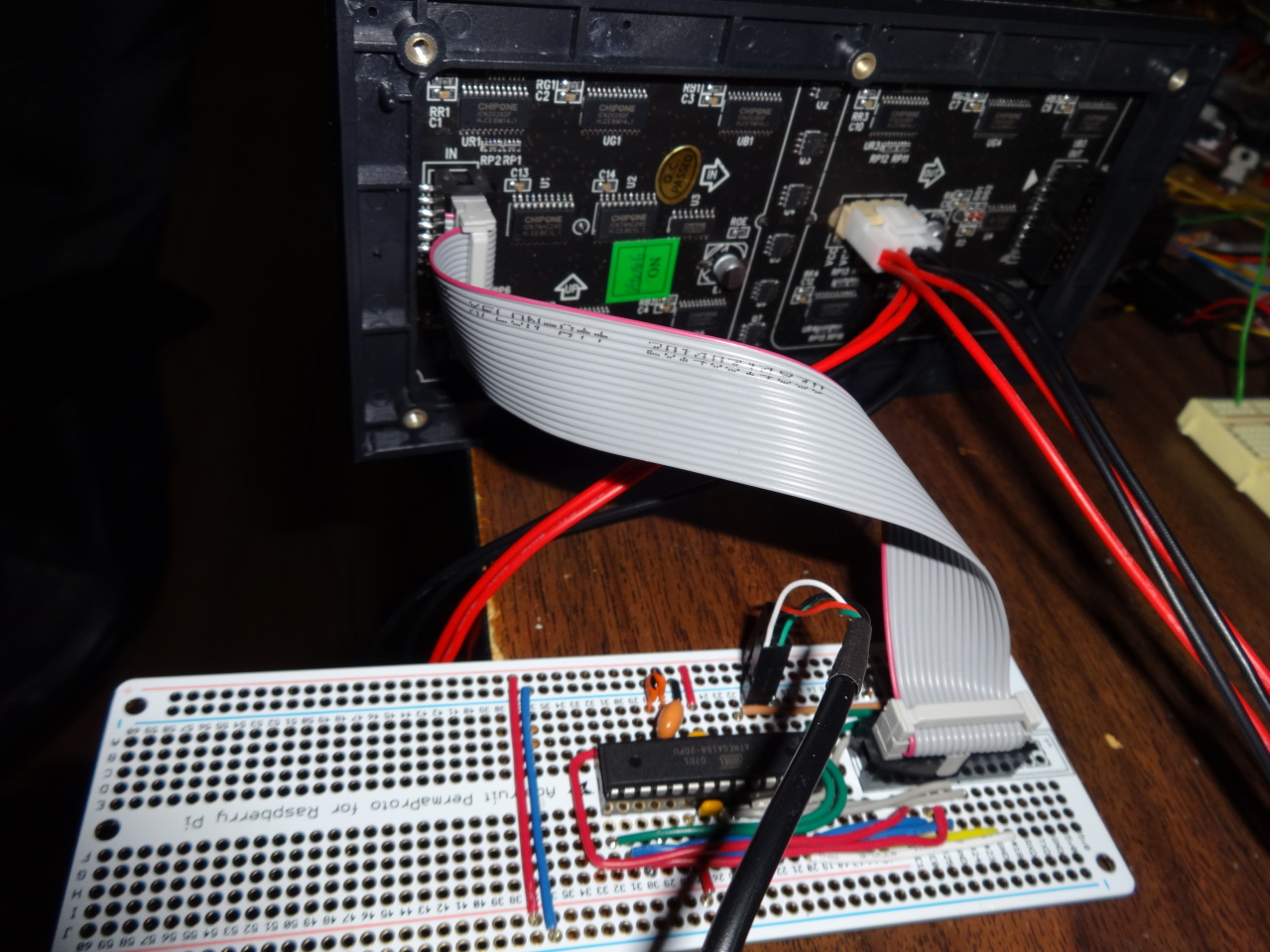
Here's the soldered circuit board connected to the LED panel.
Source code
git clone https://github.com/mikeakohn/led_panel.git (includes README and Python code)
Copyright 1997-2026 - Michael Kohn
