WS2812 ATtiny85
Posted: September 14, 2014
Introduction
I got an 8x5 NeoPixel LED panel from Adafruit with a grid of WS2812 LED's and decided to make some control circuit for it with an ATtiny85. The idea being a computer (PC or Raspberry Pi, etc) could send commands over a UART to the ATtiny85 and the ATtiny85 could control the color on the LED's.
Since the ATtiny85 doesn't have a hardware UART, I started by getting a software UART I made for another project to work at 20MHz and 9600 baud on this chip. I then wrote the code to send the first 120 bytes of the ATtiny85's RAM to the string of WS2812 LED's. The concept (and programming) is pretty simple. The data line is kept low until data is to be sent at which time it sends a sequence of keeping the line high for either 0.35uS or 0.7uS depending on if it's a zero or a one and then keeping the line low for 0.8uS or 0.6uS depending on if it's a zero or one. The on time makes sense to me, but the off time looks like an error in the datasheet or something (which wouldn't suprise me.. I think whoever wrote this awful datasheet must have been drunk). After the line is kept low for at least 50uS the bitstream from the micro is considered done. The bit stream itself is 8 bits green, 8 bits red, 8 bits blue starting at the first LED. So if I want to set LED 0 to (0,255,0) and LED 1 to (255,0,0) I would send 6 bytes of: 0, 255, 0, 255, 0, 0.
So to reduce the number of bytes that have to be written over the UART I created a command sequence:
index, r, g, b       Change pixel color at index
0xff, 0xff,          Refresh LED's with what currently is in RAM
0xff, 0xfe, r, g, b  Set all pixels to this color
0xff, 0xfd           Shift all pixels left (for string LEDS)
0xff, 0xfc           Shift all pixels right (for string LEDS)
0xff, 0xfb           Shift all pixels left (for 8x5 panel of LEDS)
0xff, 0xfa           Shift all pixels right (for 8x5 panel of LEDS)
0xff, 0xf9           Shift all pixels up (for 8x5 panel of LEDS)
0xff, 0xf8           Shift all pixels down (for 8x5 panel of LEDS)
0xff, 0xf7, r, g, b  Set all pixels that are not 0,0,0 to this value
0xff, 0xf6, r, g, b  Subtract this (r,g,b) vector from all pixels (fade out)
0xff, 0xf5, r, g, b  Add this (r,g,b) vector to all pixels (fade in?)
So basically all of the commands above simply modify the RAM in the ATtiny85. When the user wants to display what's in RAM the 0xff 0xff command is sent to the chip. This way the user can draw multiple pixels in RAM and not have to worry about the ATtiny85 being refreshing the LED string until the user is ready. So for example, I could send over the UART: 3, 255, 0, 0 which would set pixel 3 to red in RAM, but not show up on the LED's yet. Then I could do 0xff, 0xfa and pixels will shift right in RAM (so pixel 3 is off and pixel 4 is on). Still nothing shows up on the LED's until I send 0xff 0xff.
To make this easier I made a Python module (included in the git repository for this) called ws2812.py. With this module I could do the above example with:
leds = ws2812("/dev/ttyUSB0")

leds.set_rgb(3, 255, 0, 0)

leds.shift_right_8x5()

leds.refresh()
Related Projects @mikekohn.net
| Artwork: | XOR Gate, Motion Eyes, WS2812 LED, LED Panel, Half Adder, Cyborg Chicken, Electric Cat Fight, Iced Electronics |
Video
Here's a video of the circuit running demo.py from the git repository. The LED's are so bright in this video that they overwhelm the camera quite a bit. Pretty wild since each color byte can go from 0 to 255 and the Python code never takes any color component over 100. https://youtu.be/XBYZlVCpPSE
Pictures
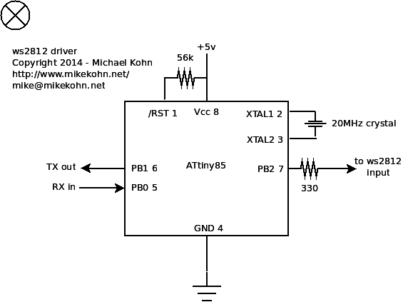
And here's the schematic...
Source code and hexfile
git clone https://github.com/mikeakohn/ws2812_driver.git (includes README and Python code)
ws2812_firmware.asm
ws2812_firmware.hex
Copyright 1997-2026 - Michael Kohn
