MIPS FPGA
Posted: January 19, 2025
Introduction
This was probably a pretty pointless project since I already did a RISCV FPGA core for a simple 32 bit processor to use, but... there are things about RISC-V that kind of bother me. It feels to me like MIPS is a bit simpler to use and easier to make an assembler for... and in some ways cleaner. Since I already did the RISC-V project, it seemed like this would be a very simple, fast project: just take the source from RISC-V and change the instruction decoding part to MIPS. Because of that, since the RISC-V project is little endian this MIPS core ended up being little endian too.
My second reason for this is to learn how to do pipelining. Have to see about this one.
This project again uses an iceFUN FPGA board.
This page is a work in progress and more info will be added...
Related Projects @mikekohn.net
| FPGA: | FPGA VGA, Nexys2, Glow In The Dark Memory, Intel 8008, F100-L, RISC-V, x86 / 68000, MIPS, MSP430, PowerPC, W65C832, Apollo 11, PDP-11 |
Video
At the time of this writing, the core MIPS runs at 6MHz while the peripherals module runs at the full 12MHz.
The four buttons are:
- Upper right: reset
- Upper left: program select (holding down on reset loads from EEPROM)
- Lower right: halt
- Lower left: user button
The rows of LEDs are used for debugging. The rows of LEDS (from left to right) are:
- Bits 0 to 7 of register t1
- Bits 8 to 15 of register t1
- Lower 8 bits of program counter
- CPU state register (fetch, decode, halt, etc)
MIPS
The first step in this project was to copy all the source files from the RISC-V project into a new repo and name riscv.v to mips.v. The code that does all the decoding in the STATE_START_DECODE state was removed. The code that does load / store and other things was able to stay mostly as-is.
To figure out how to decode all the opcodes, the first step was to break up all the instruction by their type: R-Type, I-Type, and J-Type. Then each opcode was broken up by their bit encoding and sorted by opcode. All the instructions were listed out in the README.md file of the git repo.
After getting an idea of how the opcodes were broken up by bit encoding, it was just a matter of coding that up in Verilog.
Two of the things that really make me like MIPS better than RISC-V are that some of RISC-V's instruction encodings have permutated bits and MIPS has unsigned immediates for logic instructions. MIPS's immediates are also 16 bit while RISC-V are 12. Seems like 16 bits makes it easier for writing code.
So starting with the unsigned immediates... the first thing that makes unsigned immediates nicer is for loading 32 bit values. With both MIPS and RISC-V it can take 2 instructions to load 32 bits. Typically this is aliased by the assembler using "li", which is quite a bit simpler to do in MIPS than RISC-V. An example is loading an immediate 32 bit value of 0x12349978. With MIPS the two instructions and their immediate values are simple:
  li $t0, 0x12349978

0x00000000: 0x3c081234 lui $t0, 0x1234                          cycles: 1
0x00000004: 0x35089978 ori $t0, $t0, 0x9978                     cycles: 1
In MIPS, the upper 16 bits are loaded with a straight forward 0x1234 (lui clears out the bottom 16 bits of the register) and the lower 16 bits are loaded with a simple "or" of 0x9978. Very readable from the disassembly. Since RISC-V doesn't have unsigned immediates, the load upper doesn't look like the original 0x12349 and loading the lower 12 bits is an awkward negative number.
  li t0, 0x12349978

0x00000000: 0x1234a2b7 lui t0, 0x01234a
0x00000004: 0x97828293 addi t0, t0, -1672 (0x000978)
Again, the li instruction alias takes care of the awkwardness in RISC-V but if a piece of code is already assembled, this makes disassembling and understanding the code a bit more complex.
The other thing that gets to me with RISC-V is the permutation of bits in the opcode encodings. For example, the encoding of the jal instruction has an immediate value that looks like this:
RISC-V bit encoding of jal:

  imm[20|10:1|11|19:2], rd[5:0], 1101111

Verilog code:

  pc <= $signed(pc_current) + $signed( {
    instruction[31],
    instruction[19:12],
    instruction[20],
    instruction[30:21],
    1'b0
  } );
Writing an assembler for that is much worse. Seems like both the Verilog and C code for an assembler to encode and disassemble that is open to bugs that might not be easy to catch. The reason for the permutation is supposedly for efficiency. MIPS encodes everything straight forward. An assembler disassembler is a simple mask/shift.
Something I don't like about MIPS, although other RISC CPUs for some reason do something similar for some reason, the destination register during the writeback state isn't always the rd register. For example:
The xor instruction writes back to the rd register:

  xor rd, rs, rt

While the ldw instruction writes back to the rt register:

  ldw rt, 0(rs)
Memory
RISCV FPGA and
Mandelbrots
The mandelbrot code in the lcd.asm example program was translated directly from the RISC-V project to the MIPS. Mostly this involved just register renaming, but there were some pieces of code that were able to be optimized due to the 16 bit unsigned immediates of the MIPS instruction set. An example:
RISC-V:

  li t1, 0xffff
  xor a1, a1, t1
  addi a1, a1, 1
  and a1, a1, t1

MIPS:
  xori $a1, $a1, 0xffff
  addi $a1, $a1, 1
  andi $a1, $a1, 0xffff
The MIPS code is a little easier to read too.
Improvements
There are two things I'd to improve with this implementation. The first is all instructions take 5 CPU cycles to run. It should be possible to make this 4 cycles by using the negative edge of the clock to end a memory cycle, which would remove the STATE_FETCH_OP_1 state. Not sure how that affects the register file being put in BRAM by nextpnr though. The second thing I'd like to do is pipeline this.
iceFUN
I originally used the iceFUN board with the Glow In The Dark Memory project. This was really the most perfect board for this project for me. It has 4 buttons, a grid of 8x4 LEDs for debugging, opensource tools that I could use from a simple Makefile, lots of pins, and a piezo speaker. It's also one of the cheaper FPGA boards I've seen.
Memory Map
The memory map for this project consists of 4 banks:
- Bank 0: 0x0000 RAM (4096 bytes)
- Bank 1: 0x4000 ROM (4096 bytes, an LED blink program from blink.asm)
- Bank 2: 0x8000 Peripherals
- Bank 3: 0xc000 RAM (4096 bytes)
On startup, by default the code in bank 1 (hardcoded by the file rom.v) will run. To run code starting at location 0xc000, the push button connected to C6 on the FPGA should be held down while the system is being reset.
The peripherals bank contains the following locations:
- 0x8000: input from push button
- 0x8004: SPI TX buffer
- 0x8008: SPI RX buffer
- 0x800c: SPI control: bit 2: 8/16, bit 1: start strobe, bit 0: busy
- 0x8018: ioport_A output (in my test case only 1 pin is connected)
- 0x8024: MIDI note value (60-96) to play a tone on the speaker or 0 to stop
- 0x8028: ioport_B output (3 pins)
Pictures
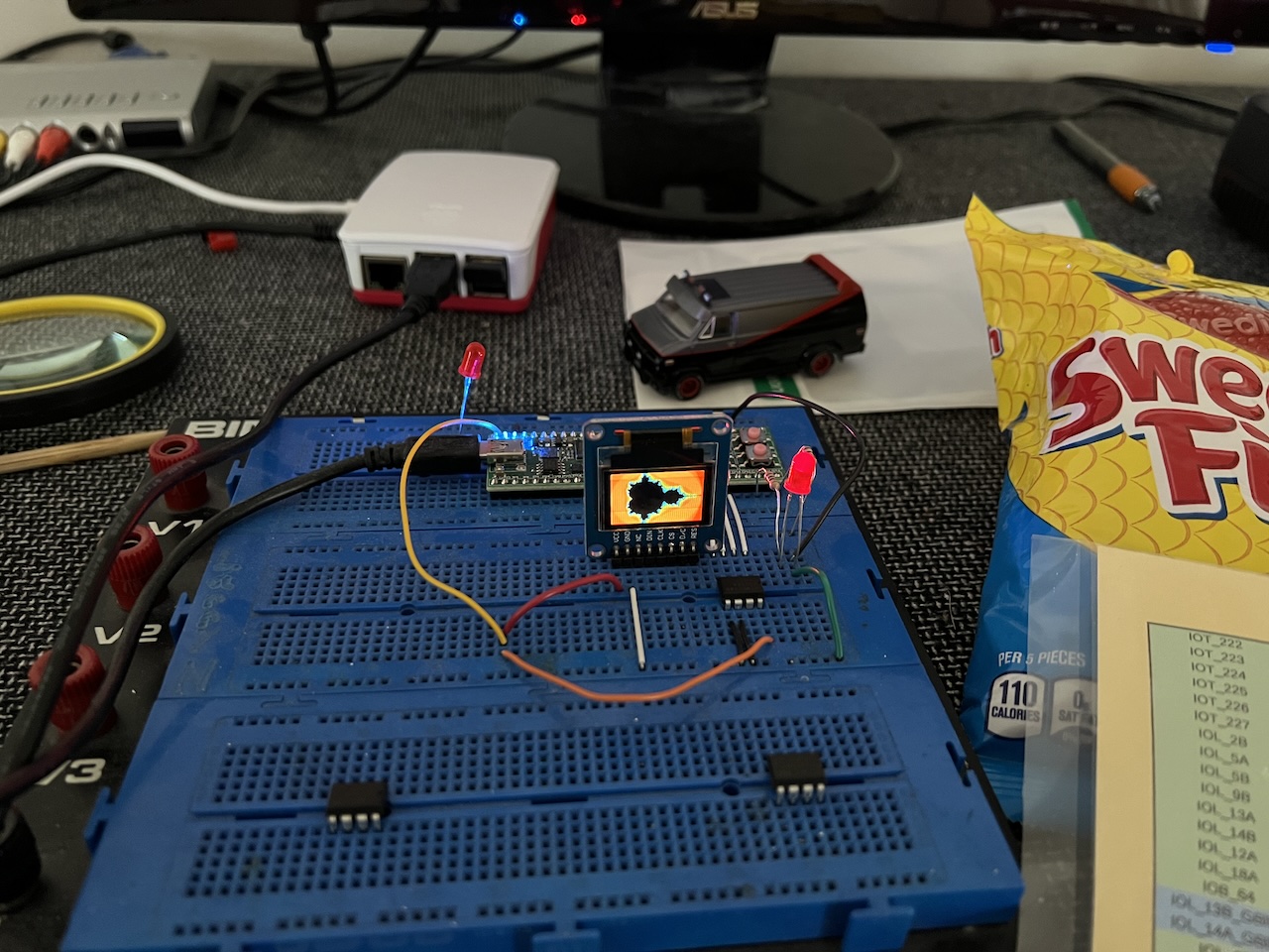
Here's the iceFUN board showing a Mandelbrot. It's connected to a Raspberry PI 5 which because all the FPGA tools are opensource can also be used for building the project.
Source code
https://github.com/mikeakohn/mips_fpga
Copyright 1997-2026 - Michael Kohn
