Edible MIDI Keyboard
October 13, 2025
Introduction
Since it's possible to buy edible underwear but not possible to buy an edible MIDI keyboard, I decided I needed to make one.
The project consists of 8 white / 5 brown Kit Kat bars sitting on top of buttons that are connected to an Atmel ATtiny2313 microcontroller. When buttons are pushed, the ATtiny2313 transmits a "note-on" MIDI command to an M5Stack Unit MIDI (SAM2695) which plays the sound. Releasing the keys sends a "note-off" command.
Video, bigger explanation, and source code below.
Related Projects @mikekohn.net
| Food: | RC Food, PANCAKE-ROM, Cyborg Chicken, Cyborg Lobster, Edible MIDI Keyboard |
| MIDI: | MIDI SN76489, Edible MIDI Keyboard |
Video
YouTube: https://youtu.be/_pIVAVvN8Uo
The video above shows a quick view of the assembly of the project. The song that is being played... well, it seemed like the only appropriate song for this project. The keyboard itself is kind of hard to play. The keys are pretty far apart and they aren't really tied down. So pushing either a little to the left or right could cause it to twist. Pushing too close to the front could cause the key to pivot forward over the button below it.
Explanation
The keyboard itself is made out of cardboard. This kind of gives it that vintage 1970's woodgrain look... except cheap. There are 13 slots for 13 keys made from cardboard taped together. For each key slot I broke off a piece of the Kit Kat bar and placed them in each slot. Each piece also sits on top of a button which on one end is connected to ground and on the other end connected to a digital I/O pin of the microcontroller.
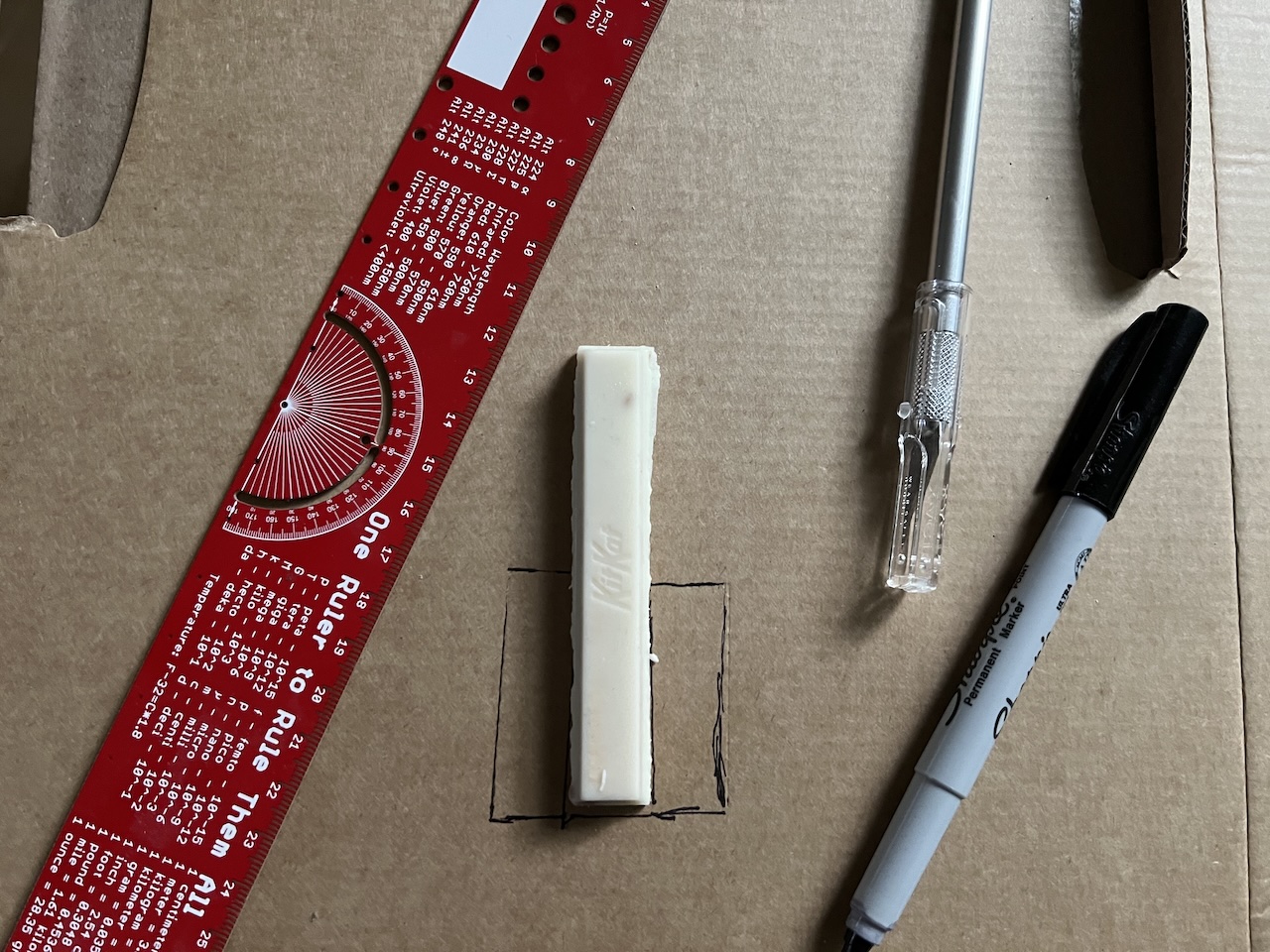
Above is a picture of how the cardboard was cut for the keys.
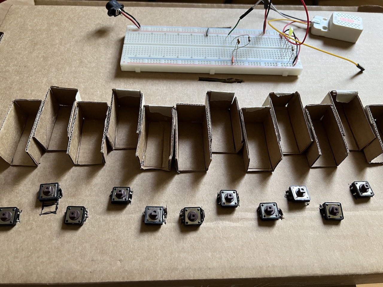
And here is a picture of the cardboard slots glued in and the 13 push buttons in place.
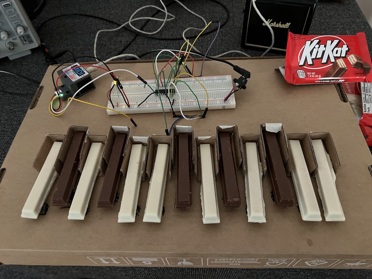
Finally, the finished keyboard with all the buttons wired up to the microcontroller and all the keys in place on top of the buttons. There is a mess of wires on the inside of the box, but I forgot to take a picture.
Kit Kats
Kit Kats were just the obvious choice for this project. Not sure if there are other candies that could look like keyboard keys. I got lucky and was able to find a pack of 8 king sized white Kit Kats for just $1. The brown Kit Kats were in a pack of 4 and regular price.
A lot of hand washing was done while working on the project since the chocolate tended to melt a little on the fingers.
M5Stack MIDI
I ended up ordering these M5Stack Unit MIDI and M5Stack MIDI Synth module back in April. The devices are based on a SAM2695 chip that can take commands over MIDI or a UART. The MIDI Synth has a built-in speaker which made it easy to test things while the Unit MIDI has a 1/8" jack which makes it possible to hook up to a nice amplifier. I had been working on a program (for another project) called parse_mid which was used to creating a play_mid program in order to test these devices.
Unfortuantely both the UNIT MIDI and MIDI Synth require a baud rate of 31250, but Linux doesn't directly support that for UART. I had to do some tricks to get the proper baud rate by setting it to 38400 in software and changing the hardware divisor with:
setserial -a -g /dev/ttyUSB0
setserial -v /dev/ttyUSB0 spd_cust divisor 768
setserial -a -g /dev/ttyUSB0
ATtiny2313
The microcontroller used for this project is the Atmel ATtiny2313. The reasoning for this chip is because it can run at 5v, the same voltage required for the M5Stack MIDI modules, along with having enough input pins for 13 keys and a hardware UART. The code is written in AVR8 assembly and assembled with naken_asm.
The ATtiny2313 can use different clock sources to run the CPU including built in calibrated RC oscillators running at either 4MHz or 8MHz. For this project, 8MHz seemed to make the most sense. Unfortunately, using the standard calculation provided in the ATtiny2313 datasheet for the UART speed did not provide the correct baud rate (lots of data glitches) so to make this work the Baud Rate Register setting had to be changed by 1:
  ;; Set up UART baud rate.
  ;; 9600 for a computer, 31250 for MIDI.
  ldi r17, ((8_000_000 / (8 * BAUD_RATE)) - 1) >> 8
  out UBRRH, r17
  ;ldi r17, ((8_000_000 / (8 * BAUD_RATE)) - 1) & 0xff  <-- proper
  ldi r17, ((8_000_000 / (8 * BAUD_RATE)) - 0) & 0xff   <-- one off
  out UBRRL, r17
My best guess is the 8MHz internal oscillator wasn't accurate enough. It's possible to put a 8MHz (or up to 20MHz) resonator on the XTAL pins and use that for an accurate source, but less parts is sometimes better.
Flashing Firmware
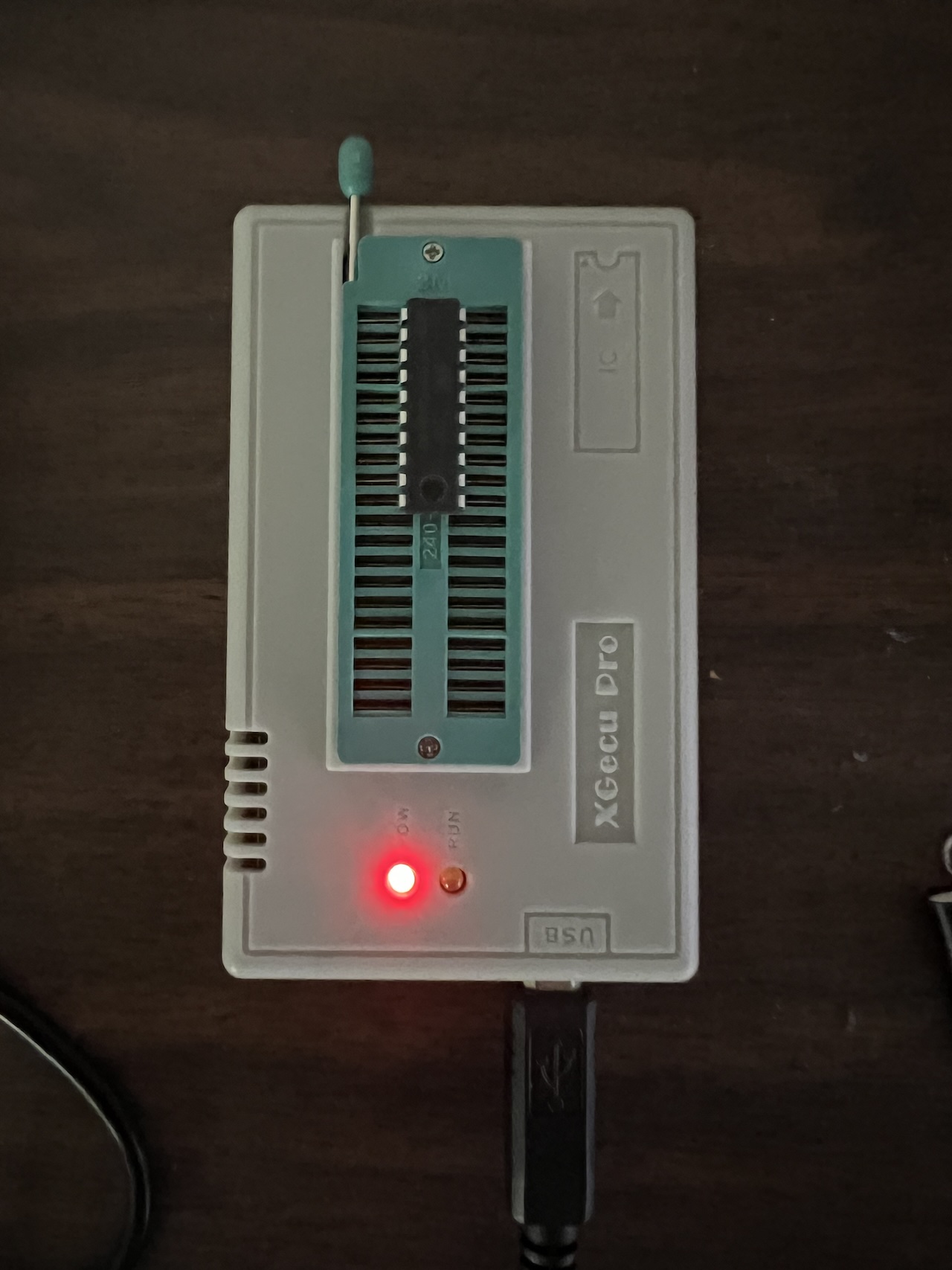
Usually I program Atmel ATtiny2313 chips with some hardware such as the AVR Dragon along with the avrdude software. This time I decided to try it with the TL866 II+ programmer and minipro software. It seemed like the Dragon wouldn't work as well for this since 4 pins that were being used for digital I/O were needed for the programming wires.
To program with the TL866 II+ the chip is aligned in the ZIF socket with pin 1 at the far top of the programmer like this:
With avrdude, the fuses in Atmel AVR chips are set using a command option for changing the fuses. WIth the TL866 II+ the fuses are set by creating a text file and using the -c config option. The text file could look like this:
lfuse = 0xe4
hfuse = 0xdf
efuse = 0xff
lock = 0xff
Sadly, any time a hexfile is flashed to the chip, the fuses are reset. So after writing the hexfile the fuses have to be set. Here's an example of using minipro to write the hexfile, write the config, and then read the config file back to make sure it worked:
./minipro -p ATTINY2313A@DIP20 -w edible_midi.hex
./minipro -p ATTINY2313A@DIP20 -w config.txt -c config
./minipro -p ATTINY2313A@DIP20 -r config.new -c config
Source Code
https://github.com/mikeakohn/small_projects/tree/main/edible_midi_keyboard
Copyright 1997-2026 - Michael Kohn
